Using earth leakage relays to monitor variable frequency drives (VFDs) is a critical application in industrial automation. Since VFDs generate unique high-frequency harmonics and DC leakage currents during operation, traditional residual current circuit breakers (RCCBs) are often unable to handle them effectively. Therefore, a special type-B earth leakage relay is required to cooperate with the circuit breaker(MCCB/MCB) to achieve reliable protection.
The leakage current in the VFD system primarily comprises the leakage current on the input side of the VFD line, the leakage current at the VFD output end, and the leakage current on the motor cable. In the industrial automation inverter system, a type B earth leakage monitoring relay is mainly required on the inverter input side to cope with its special leakage current characteristics and ensure electrical safety and production continuity.
The core of the leakage current protection relay (usually composed of a zero-sequence current transformer and an ELR relay body) monitoring the VFD line is the current vector balance method:
When operating normally without faults, the inflow and outflow of all currents in the circuit are balanced. This means that the current vector sum of all phase lines and neutral lines (if any) at any time is zero. When these wires pass through the zero-sequence current transformer (ZCT), the magnetic fields they generate cancel each other out, and there is no current output on the secondary side of the ZCT.
When a ground fault occurs: Once the insulation to the ground of the inverter line (such as the inside of the inverter, the motor or the motor cable) is damaged, or someone accidentally touches the live part, part of the current will “leak” out of the normal circuit and flow to the ground. This breaks the balance of the current in the ZCT, causing a non-zero current to be induced on its secondary side, which is the residual current.
Relay action: The leakage current protection relay body receives the residual current signal sensed by the ZCT. When this residual current reaches the preset action threshold of the relay (such as 30mA, 100mA, 300mA, etc.), the earth leakage relay will immediately issue a trip command (usually a dry contact signal).
Circuit breaker cuts off the power supply: The trip command of the relay will be sent to the shunt release of the circuit breaker (such as MCCB or MCB) in the main circuit. After receiving the command, the circuit breaker will quickly (milliseconds) cut off the main power supply of the inverter, thereby isolating the fault and protecting personnel safety and equipment from damage.
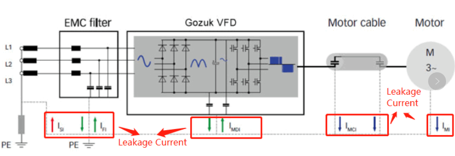
Here’s a common wiring diagram for using a Type B earth leakage relay to monitor a three-phase VFD line.
Wiring Explanation:
Main Power: The three-phase (R, S, T) or three-phase four-wire (R, S, T, N) power supply connects here.
Circuit Breaker (MCCB/MCB): Installed on the supply side, this provides overload and short-circuit protection for the VFD.
It must have a shunt trip coil (or undervoltage release, depending on the relay’s output) to receive the trip signal from the leakage current protection relay. When the shunt trip coil is energized, the breaker trips immediately.
Zero Sequence Current Transformer (ZCT): All phase wires (R, S, T) must pass through the ZCT’s central opening. If it’s a three-phase four-wire system (with a neutral), the neutral wire (N) must also pass through the ZCT. Make sure only the VFD circuit’s wires go through the ZCT, not any other circuits. The ZCT’s secondary output (usually two wires) connects to the leakage current protection relay module’s ZCT input terminals.
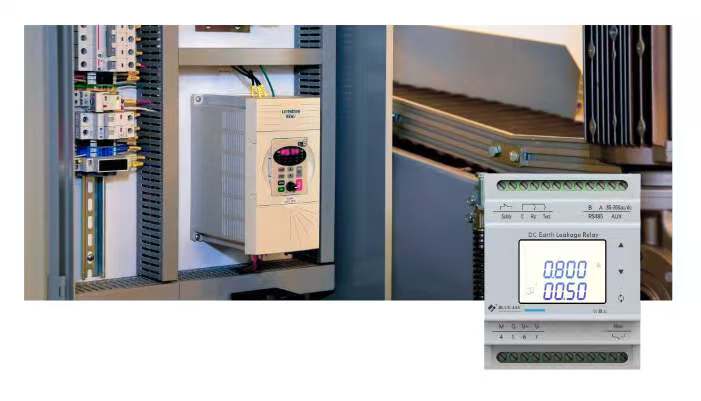
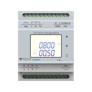
Leakage Current Protection Relay Module
Power Supply: The relay module needs its control power (typically 220V AC or 24V DC) to operate.
ZCT Signal Input: Connects to the ZCT’s secondary output.
Trip Output: The relay module provides one or more dry contact (normally open/normally closed) outputs. Connect this output to the control circuit of the circuit breaker’s shunt trip coil. When the relay trips, it closes the contact, energizing the shunt trip coil and causing the breaker to trip.
Test/Reset Buttons: The relay typically has test buttons (for periodic checks) and a reset button (to manually reset after a fault).
VFD (Variable Frequency Drive): The output of the circuit breaker connects to the VFD’s power input terminals.
Motor & Cable: The VFD’s output connects to the motor.
With the above solution principle and wiring diagram, you can provide economical and reliable leakage current protection for VFD lines in industrial automation environments. To know more about the earth leakage relay for VDF, please send an enquiry to us now.