
Four insulation monitoring device circuit Solutions
Insulation monitoring device circuit solutions are essential for ensuring
IEC 60364 defines three types of earthing systems: TN earthing system, TT earthing system, and IT earthing system. The TN earthing system is subdivided into the TN-S earthing system, TN-C earthing system, and TN-C-S earthing system.
What do these letters of the earthing system mean?
T: stands for the direct connection to the earth.
I: stand for Isolated.
N: stands for Neutral.
S: stands for Separate.
C: is combined.
How do they combine?
The first letter of each system is associated with the type of earth connection of the network, which refers to the power source from a start-connected winding. We use the letter T if there is a direct connection to Earth in the transformation center. Normally, for the neutral tap of the transformer, we use the letter I if the active parts of the installation are isolated from the ground or if there is a connection point through a high impedance therefore if the power supply is grounded directly and on the other hand I if it is connected with an impedance or isolated that is infinite.
The second letter is associated with the type of connection of the masses of the loads ( eg, electrical machines), which refers to the consuming equipment that needs to be earthed. We use the letter T to indicate the type of connection to the ground of the masses of the customer’s loads. Suppose these are connected directly to a ground independent of one of the distribution systems. The second letter can also take the value N in case the masses of the loads are connected directly to the grounded point of the transformer, which for a three-phase installation.
We use the letter T if there is a direct connection to Earth in the transformation center. Normally, for the neutral tap of the transformer, we use the letter I if the active parts of the installation are isolated from the ground or if there is a connection point through a high impedance therefore if the power supply is grounded directly and on the other hand I if it is connected with an impedance or isolated that is infinite. And for the second letter that indicates type of connection about ground of the masses of the customer’s loads that is their metal enclosures we use letter T. If these are connected directly to a ground independent of the one of the distribution system. the second letter can also take the value N in case the masses of the loads are connected directly to the grounded point of the transformer which for a three-phase installation.
TT earthing system
In this earthing system, the connection to the supply source is directly connected to the earth, and the load end or installation metalwork is also directly connected to the earth. Therefore, in the case of an overhead line, the mass of the earth will be the return path for the line. The neutral and earthen conductors must be separated during the installation because the power distributor only provides the supply neutral or protective conductor for the connection to the consumer.
IT earthing system
The IT system does not have any connections to Earth, or it has only a high-impedance connection. the basic feature of the IT system is that in the event of a fault between phases and earth, the system can continue to operate without interruption such a fault is referred to as a first fault thus usual earthing protection is not effective for this system and this type is not meant for consumer power supply the it earthing system is usded for power distribution systems such as substations or generators.
TN-S earthing system
In this system, the ground conductor and neutral conductor are separate throughout the distribution system. The protective conductor is the metallic covering of the cable supplying the installation. all the exposed conductive parts of the installation are connected to this protective conductor or via the main earthing terminal of the installation.
TN-C earthing system
In TNC earthing system the neutral and protective earth are combined into a single conductor throughout the system all the exposed and conductive parts of the insulation are connected to the pen conductor as per section 8-4 of the electrical safety quality and continuity regulations from 2002 from the UK Consumer shall not combine the neutral and protective functions in a single conductor in his customers installation.
TN-C-S earthing system
In the TN-C-S system, the neutral and protective earth are combined into a single conductor in a part of the system. This type of earthing is also known as multiple protective earthing the supply system pen conductor is earth at two or more points and an earth electrode may be necessary at or near the consumer’s installation. All the exposed conductor parts of the insulation are connected to the pen conductor via the main earthing terminal and the neutral terminal, and these terminals are linked together.
Each earthing system requires specific protective devices to ensure personal safety and system reliability in the event of a fault:
In TT systems, Residual Current Devices (RCDs) are mandatory to detect leakage currents to earth and quickly disconnect the supply to prevent electric shock. In addition, Overcurrent Protective Devices (MCBs/MCCBs/Fuses) are used to protect against overcurrent and short-circuit faults.
TN systems rely primarily on Overcurrent Protective Devices (MCBs/MCCBs/Fuses) to clear earth faults quickly through the low-impedance fault path provided by the earthed neutral connection. In TN-S and TN-C-S systems, RCDs can also be installed for supplementary protection, particularly in residential or commercial applications.
In IT systems, since the first earth fault does not immediately disconnect the power supply, Insulation Monitoring Devices (IMDs) are essential to continuously supervise insulation resistance and issue alarms upon detecting a fault. Additionally, Overcurrent Protective Devices (MCBs/MCCBs) are required for overcurrent and short-circuit protection. Residual Current Devices (RCDs) may also be used in specific areas to enhance personal protection.
Feature | TT Earthing System | IT Earthing System | TN Earthing System |
Power Source Neutral | Directly earthed (T) | Not earthed, or earthed via a high impedance (I) | Directly earthed (T) |
Device Earthing | Exposed conductive parts (enclosures) connected to a local, independent earth electrode (T). | Exposed conductive parts connected to a local, independent earth electrode (T). | Exposed conductive parts connected to the earthed neutral of the power source (N). |
First Earth Fault Behavior | RCD (Residual Current Device) trips quickly, cutting off power. | Does not trip, the system continues to operate; IMD (Insulation Monitoring Device) alarms. | High fault current causes fast tripping by overcurrent protective devices (MCBs/MCCBs). |
Supply Continuity | Lower (power is interrupted on first fault) | Highest (supply continues on first fault) | Higher (fault is cleared quickly, but supply is interrupted) |
Personal Safety | High (excellent shock protection via RCD) | High (very small fault current on first fault, but requires timely repair) | High (fast fault clearance; TN-S generally best for safety) |
Fault Current | Relatively small (limited by local earth resistance) | Extremely small (limited by system insulation and capacitance) | Large (limited by circuit impedance) |
Required Protection | Residual Current Devices (RCDs) are mandatory. | Insulation Monitoring Devices (IMDs) are mandatory. | Overcurrent Protective Devices (MCBs/MCCBs/Fuses); RCDs can be used for supplementary protection in TN-S/TN-C-S. |
Cost & Complexity | Moderate (RCDs and local earth electrodes) | Higher (IMDs, specialized maintenance) | Lower (TN-C), Moderate (TN-S/TN-C-S) |
Primary Advantage | High personal safety, relatively simple installation. | Extremely high supply continuity, low fire/explosion risk on first fault. | Fast fault clearance, relatively lower cost (TN-C). |
Primary Disadvantage | Every fault causes power interruption; relies on RCDs. | Complex management; requires professional maintenance; risk if second fault occurs before first is cleared. | TN-C has safety risks if PEN conductor breaks; potential EMC issues with TN-C. |
Insulation monitoring device circuit solutions are essential for ensuring
DC insulation monitoring device (IMD) is a well-known insulation
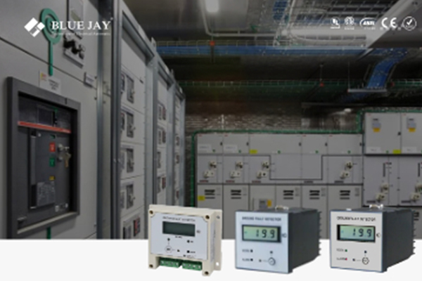
Insulation monitor is widely used in DC Charging Stations, DC