Why the General Industrial Transducer Signal Is 4 to 20 mA?
It is common in the industry to measure various

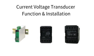
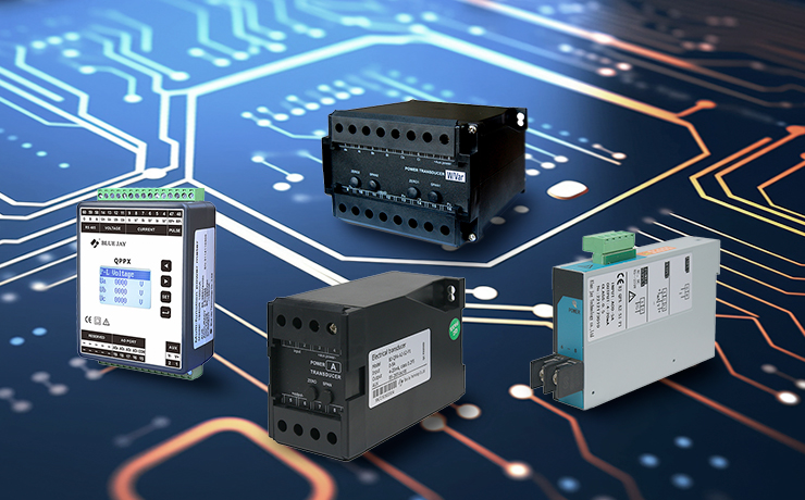
The current voltage transducer is a device that converts the measured AC voltage/current, DC voltage/current, and pulse voltage into linearly proportional output DC voltage or DC current and isolates the output analog signal or digital signal. Thus, someone calls them a voltage transducer or current transducer.
The current voltage transducer technician tells you that the voltage transmitter measures the AC voltage, DC voltage, or pulse voltage after conversion, and is an output DC voltage (0-5V) or DC Current (4-20mA) and isolated analog or digital signal output instrumentation. So, what is the function of the voltage transducer? The details are as follows:
1. The output of the installed voltage transducer is two-wire 4-20 mA, with no need for a separate output power line, and the lead wire can use very cheap and thin wires; it can save a lot of cable and installation costs.
2. When the output resistance of the current source is large enough, the current caused by the interference source is very small, and the interference can be reduced by using twisted pairs, so the voltage in the conductor loop cannot be caused by magnetic field coupling.
3. Due to the large voltage, the voltage transducer produced by Blue Jay Electrical can directly collect 500 VAC and convert it into a standard signal to realize decentralized collection, which has the advantages of decentralized collection and centralized control.
4. Applying 4mA to the zero level makes determining open and short circuits, as well as sensor damage (0mA state), very simple.
5. The input, output, and power supply of the voltage transducer are completely isolated, and the performance is stable.
Many people may want to know how the current voltage transducer is installed. The power transducer can be used in many places, so how should you order it correctly?
Measure the power supply of the current voltage transducer, whether there is a 24V DC voltage or not. It must be ensured that the power supply voltage of the power transducer is ≥12V (that is, the voltage at the input terminal of the transducer power supply is ≥12V). If there is no power source, see if the circuit is closed or if the instrument was chosen improperly (the input impedance should be 250). If there is a meter, check whether the meter is damaged, you can short-circuit the two wires of the meter first, if the short circuit is normal, it indicates that the meter is broken, and a broken meter requires replacement.
Connect the ammeter to the 24V power supply circuit to check whether the current is normal; if the current is normal, check other instruments in the circuit. Regardless of whether the power supply is connected to the power input terminal of the power transducer, please connect the power cord to the power terminal.
Whether the power supply of the power transducer is normal. Check to see if the circuit has a big load. The power transducer load input impedance must match the real pressure of RL (transmitter power supply voltage -12V)/(0.02A), which exceeds the pressure transmitter’s chosen range. Re-choose the proper pressure transmitter range, check to see if the pressure sensor is damaged, and return the device to the manufacturer for repair if the isolated diaphragm has been damaged by a significant overload.
Whether the power supply of the power transducer is normal. If less than 12 VDC, you must check for heavy loads in the circuit. The input impedance of the power transducer load should comply with the pressure value indicated by RL ≤ (transducer power supply voltage-12V)/(0.02A)Ω. If the reference gauge is less accurate, the gauge must be replaced with a higher-accuracy gauge.

It is common in the industry to measure various

With the increasing degree of automation of the electrical

An electrical transducer is a device that converts a


