the application low-voltage intelligent motor protection controller
1 Introduction
The electrical equipment of the steel manufacturing industry belongs to continuous operation with large capacity and high load. Therefore, its reliability and stability requirements are high. Once an accident occurs, the cause of the failure must be found immediately and eliminated in time to ensure timely recovery of production.

2 Causes of motor failure
The motor is running due to various reasons. There will be malfunctions, which are divided into mechanical and electrical aspects.
2.1 Mechanical failures such as bore sweeping, vibration, bearing overheating, etc.
2.2 The main electrical aspect is that the motor windings are overheated and burned when they exceed the rated value.
Here we only analyze the electrical faults. One of the main reasons for the overheating of the windings is that the current flowing through the windings is too large, which exceeds the rated current of the motor.
The second main reason for the overheating of the winding: Although the current flowing through the winding does not exceed the rated value, it is due to poor ventilation of the motor or high ambient temperature. The heating of the winding cannot be dissipated in time, and it can also cause the temperature of the winding to exceed the rated value and burn the motor.
3 Composition and function of electric protector
3.1 The composition of the electric protector
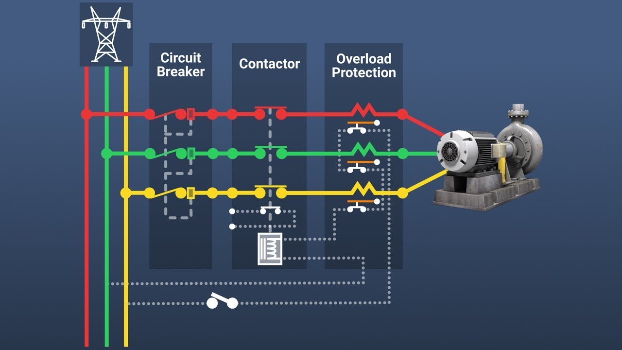
The motor protector integrates low-voltage protection such as over (light) load protection, phase loss, over (under) voltage, locked rotor, leakage, grounding and three-phase unbalance protection, etc., usually by current transformer, comparison circuit, single-chip microcomputer or export The relay is composed of several parts.
3.2 Function of motor protector
3.2.1 System protection function
The motor protector can realize the comprehensive protection of the motor. The specific functions include grounding protection, phase failure protection, short circuit protection, over (light) load protection, unbalanced overload protection, locked rotor protection, low voltage and over voltage protection. When the motor is working normally, the protector passes through the LCD display on the panel. Real-time display of the working current and voltage of the motor. When a fault occurs, the protector can react automatically and quickly and send a trip signal.
3.2.2 Fault judgment and memory function
When the motor protector detects the motor. It is necessary to correctly judge the working conditions of the motor, such as normal, overload, short circuit, open phase, overvoltage, under voltage, and overheating, and deal with it accordingly. When a certain fault occurs in the motor, the protector cuts off the power of the motor and is in a protection state, and saves the fault type, time and motor operating parameters. The motor protector recognizes, memorizes and indicates the fault through the recognition and memory circuit for easy maintenance. Only after the fault is eliminated and the protector is reset, the fault indication disappears and the electric motor can be restarted.
3.2.3 Online monitoring function
The motor protector with communication function enables the operator in the control room to read, modify and set various protection setting data of all protectors on the background computer. at the same time. Online monitoring of the running load of the motor and the quality of the power supply. This creates conditions for early detection of overloads and ground faults.

4 Application of electric protector
4.1 Selection principle
The application of the motor protector must first be the correct selection. The following aspects must be considered.
4.1.1 Motor protectors are divided according to their structure, generally divided into two types: one type and split type.
The so-called integrated type means that the display panel and the current transformer part are integrated, and the split type means that the display panel and the current transformer part are separated.
4.1.2 Motor protectors are divided according to the rated working voltage and current range, which can be divided into AC380V and AC220V; the corresponding ranges are 1A, 6.3A, 25A, 100A, 250A, etc., and they are used according to the motor control circuit. The working voltage and the rated current of the load can be selected from the corresponding range.
1 Introduction
The electrical equipment of the steel manufacturing industry belongs to continuous operation with large capacity and high load. Therefore, its reliability and stability requirements are high. Once an accident occurs, the cause of the failure must be found immediately and eliminated in time to ensure timely recovery of production.

2 Causes of motor failure
The motor is running due to various reasons. There will be malfunctions, which are divided into mechanical and electrical aspects.
2.1 Mechanical failures such as bore sweeping, vibration, bearing overheating, etc.
2.2 The main electrical aspect is that the motor windings are overheated and burned when they exceed the rated value.
Here we only analyze the electrical faults. One of the main reasons for the overheating of the windings is that the current flowing through the windings is too large, which exceeds the rated current of the motor.
The second main reason for the overheating of the winding: Although the current flowing through the winding does not exceed the rated value, it is due to poor ventilation of the motor or high ambient temperature. The heating of the winding cannot be dissipated in time, and it can also cause the temperature of the winding to exceed the rated value and burn the motor.
3 Composition and function of electric protector
3.1 The composition of the electric protector
The motor protector integrates low-voltage protection such as over (light) load protection, phase loss, over (under) voltage, locked rotor, leakage, grounding and three-phase unbalance protection, etc., usually by current transformer, comparison circuit, single-chip microcomputer or export The relay is composed of several parts.
3.2 Function of motor protector
3.2.1 System protection function
The motor protector can realize the comprehensive protection of the motor. The specific functions include grounding protection, phase failure protection, short circuit protection, over (light) load protection, unbalanced overload protection, locked rotor protection, low voltage and over voltage protection. When the motor is working normally, the protector passes through the LCD display on the panel. Real-time display of the working current and voltage of the motor. When a fault occurs, the protector can react automatically and quickly and send a trip signal.
3.2.2 Fault judgment and memory function
When the motor protector detects the motor. It is necessary to correctly judge the working conditions of the motor, such as normal, overload, short circuit, open phase, overvoltage, under voltage, and overheating, and deal with it accordingly. When a certain fault occurs in the motor, the protector cuts off the power of the motor and is in a protection state, and saves the fault type, time and motor operating parameters. The motor protector recognizes, memorizes and indicates the fault through the recognition and memory circuit for easy maintenance. Only after the fault is eliminated and the protector is reset, the fault indication disappears and the electric motor can be restarted.
3.2.3 Online monitoring function
The motor protector with communication function enables the operator in the control room to read, modify and set various protection setting data of all protectors on the background computer. at the same time. Online monitoring of the running load of the motor and the quality of the power supply. This creates conditions for early detection of overloads and ground faults.

4 Application of electric protector
4.1 Selection principle
The application of the motor protector must first be the correct selection. The following aspects must be considered.
4.1.1 Motor protectors are divided according to their structure, generally divided into two types: one type and split type.
The so-called integrated type means that the display panel and the current transformer part are integrated, and the split type means that the display panel and the current transformer part are separated.
4.1.2 Motor protectors are divided according to the rated working voltage and current range, which can be divided into AC380V and AC220V; the corresponding ranges are 1A, 6.3A, 25A, 100A, 250A, etc., and they are used according to the motor control circuit. The working voltage and the rated current of the load can be selected from the corresponding range.


