What is Synchroscope? Method & Working Principles
By xy | Industry News
What is Synchroscope?
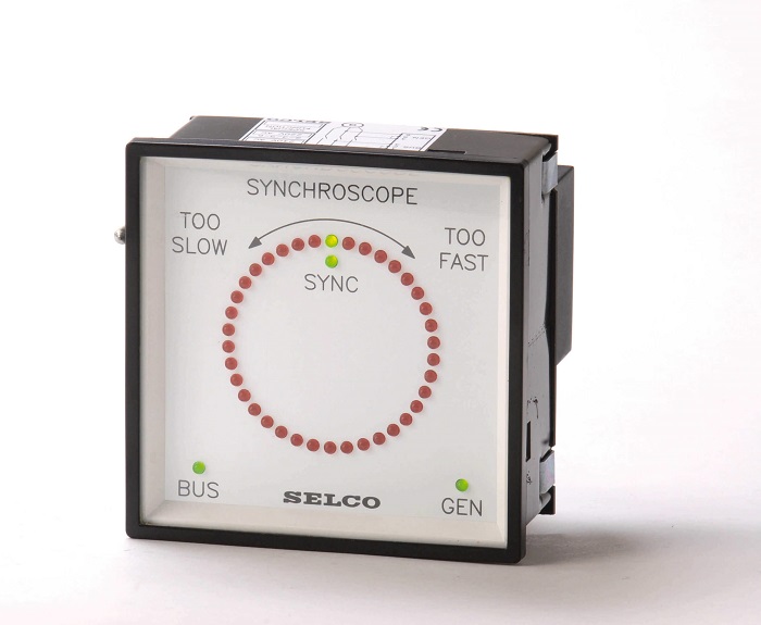
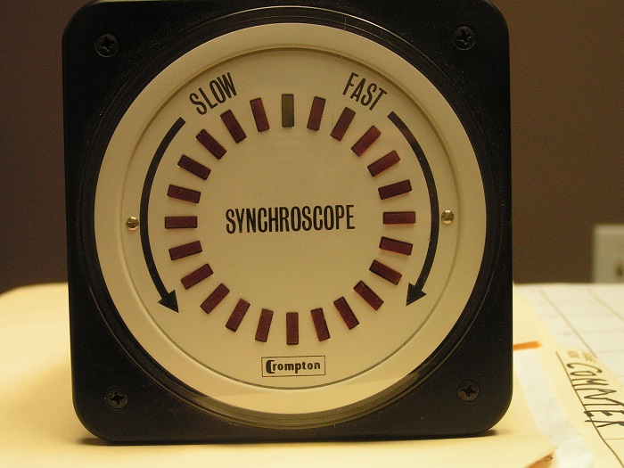
A Synchroscope is a device designed specifically to indicate if two power networks or generators (or any other AC electrical power system) are synchronized with one another. This device checks the operation of both systems to make sure they are working at the same frequency. Plus, for them to be synchronized, the phase angle of these two systems should be 0 as well. The phase sequence between two poly-phase systems, too, should be the same. So a Synchroscope is responsible for measuring and indicating the phase angle and frequency difference between two desired power systems.
This device plays a crucial role since the wrong number between the two aforementioned parameters causes severe damage to the systems that are not safely guarded by circuit breakers or fuses. This damage is due to the flow of high currents. These two numbers should be zero for the two AC power systems to be able to connect together or else, the systems are considered to be unsynchronized. A Synchroscope can also show the incoming alternator’s speed and whether it runs slow or fast.
Synchroscope structure and working principles
A Synchroscope follows simple operating principles that you need to know of when searching for the answer to “What is synchroscope?” The relative frequency difference, as well as the phase angle between two AC power systems, are measured with the help of these principles. A Synchroscope consists of a stator, a two-phase one, and a rotor. The two-phase supply to the Synchroscope is provided by the alternators.

When two of the phases are synchronized together, the third one automatically follows the process and will sync with the other two phases. The Synchroscope’s stator receives the supply from the existing alternator. The incoming alternator, then, provides the supply for the rotor. This phase shifting between the above-mentioned supplies is the sign of the difference in both frequency and phase to the connected alternators that are parallel to one another.
When the alternators with different frequencies are connected together, the device starts operating to indicate the desired parameters. When the stator’s and the rotor’s frequency stay the same, the rotor won’t rotate and the dials remain stationary. With a change in the supply’s frequency of the rotor and the stator, the rotor starts moving and as a result, the dials start deflecting. The supply frequency’s difference is the parameter that the rotor’s speed depends on. The larger the difference, the higher the speed of the rotor. And when the difference is minimal, the rotation speed of the rotor reduces as well.
Different Synchroscope types
Synchroscopes have two main types:
1. Electrodynamic type (ie, Digital Synchroscopes)
2. Moving Iron type (ie, Analog Synchroscopes)
Now let’s dive into these two types (Electrodynamic and moving iron type) to be able to learn more about “What is Synchroscope?”
Electrodynamic Synchroscope
This Synchroscope type is also known as the western Synchroscope type and includes an electrodynamic device as well as a three-limb transformer. The static and the dynamic methods of synchronization have been brought together in this Synchroscope type to achieve the correct synchronization instant. In the dynamic method, an electrodynamometer type Synchroscope will be used while in the static method, the system will need a lamp.
The static part of the Electrodynamic Synchroscope, as we mentioned above for answering “what is Synchroscope?”, contains a three-limbed transformer. The central lamp is responsible for the lamb and the two outer ones are responsible for the busbar voltage and the incoming machine voltage.
The central limb receives the fluxes made by the outer limbs. The phasor sum of the received fluxes becomes the next one in the central limb resulting in the operation of the lamp. The flux in the central limb makes the lamp grow to its highest level when the two voltages provided by the outer limb windings are in the same phase. This is exactly the opposite for when they are out of phase.
The dynamic part contains an electrodynamometer type Synchroscope. This part consists of two parts that have been divided from a fixed coil. The moving coil of this part contains a pointer. A resistor connects the fixed coil to the busbar and there’s an inductor connected to it as well. The incoming machine’s terminal is connected to the moving coil by a capacitor.
When both voltages are in the same phase, then the two currents would be in quadrature to one another and no torque will impact the pointer and remains vertical. In this part, the movement of the pointer (whether it be clock-wise or counter-clock-wise) indicates the speed of the incoming machine.

Moving iron synchroscopes
Moving iron synchroscopes, or analog synchroscopes, are used in power systems to synchronize two AC power sources, like a generator and a grid.
They visually display the frequency and phase difference, guiding operators to match the generator’s output with the grid before connection.
These devices work through electromagnetic induction: a moving iron element interacts with magnetic fields from both sources, causing a pointer to rotate. The pointer’s speed indicates the frequency difference.
While simple, robust, and cost-effective, they are less accurate and provide less information than digital synchroscopes, primarily showing frequency and phase differences. They are essential for generator synchronization in power plants.
Recomended Synchroscope

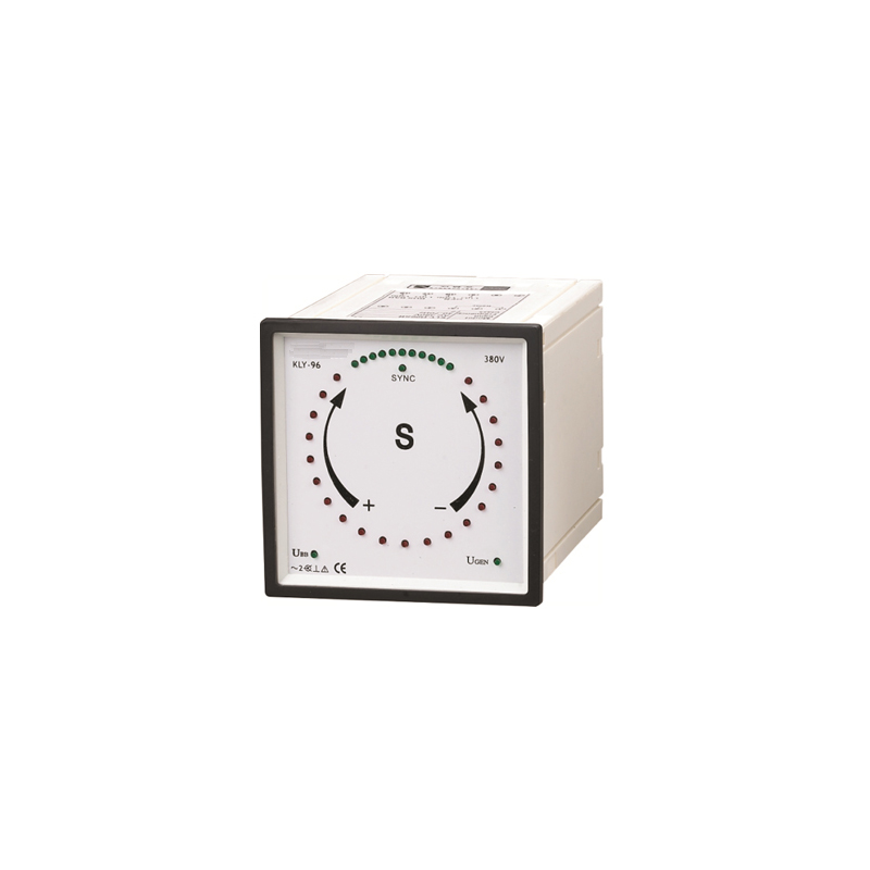
CP-S Synchroscope Meter
Blue Jay CP-S Synchronoscope Meter is used to measure the frequency and phase difference between two AC power sources.
- A pointer synchroscope or digital synchroscope optional
- 72x72mm, 96x96mm, 144x144mm Optional
- with relay output or without relay output
Tags
Industry News
What is Synchroscope?
A Synchroscope is a device designed specifically to indicate if two power networks or generators (or any other AC electrical power system) are synchronized with one another. This device checks the operation of both systems to make sure they are working at the same frequency. Plus, for them to be synchronized, the phase angle of these two systems should be 0 as well. The phase sequence between two poly-phase systems, too, should be the same. So a Synchroscope is responsible for measuring and indicating the phase angle and frequency difference between two desired power systems.
This device plays a crucial role since the wrong number between the two aforementioned parameters causes severe damage to the systems that are not safely guarded by circuit breakers or fuses. This damage is due to the flow of high currents. These two numbers should be zero for the two AC power systems to be able to connect together or else, the systems are considered to be unsynchronized. A Synchroscope can also show the incoming alternator’s speed and whether it runs slow or fast.
Synchroscope structure and working principles
A Synchroscope follows simple operating principles that you need to know of when searching for the answer to “What is synchroscope?” The relative frequency difference, as well as the phase angle between two AC power systems, are measured with the help of these principles. A Synchroscope consists of a stator, a two-phase one, and a rotor. The two-phase supply to the Synchroscope is provided by the alternators.

When two of the phases are synchronized together, the third one automatically follows the process and will sync with the other two phases. The Synchroscope’s stator receives the supply from the existing alternator. The incoming alternator, then, provides the supply for the rotor. This phase shifting between the above-mentioned supplies is the sign of the difference in both frequency and phase to the connected alternators that are parallel to one another.
When the alternators with different frequencies are connected together, the device starts operating to indicate the desired parameters. When the stator’s and the rotor’s frequency stay the same, the rotor won’t rotate and the dials remain stationary. With a change in the supply’s frequency of the rotor and the stator, the rotor starts moving and as a result, the dials start deflecting. The supply frequency’s difference is the parameter that the rotor’s speed depends on. The larger the difference, the higher the speed of the rotor. And when the difference is minimal, the rotation speed of the rotor reduces as well.
Different Synchroscope types
Synchroscopes have two main types:
1. Electrodynamic type (ie, Digital Synchroscopes)
2. Moving Iron type (ie, Analog Synchroscopes)
Now let’s dive into these two types (Electrodynamic and moving iron type) to be able to learn more about “What is Synchroscope?”
Electrodynamic Synchroscope
This Synchroscope type is also known as the western Synchroscope type and includes an electrodynamic device as well as a three-limb transformer. The static and the dynamic methods of synchronization have been brought together in this Synchroscope type to achieve the correct synchronization instant. In the dynamic method, an electrodynamometer type Synchroscope will be used while in the static method, the system will need a lamp.
The static part of the Electrodynamic Synchroscope, as we mentioned above for answering “what is Synchroscope?”, contains a three-limbed transformer. The central lamp is responsible for the lamb and the two outer ones are responsible for the busbar voltage and the incoming machine voltage.
The central limb receives the fluxes made by the outer limbs. The phasor sum of the received fluxes becomes the next one in the central limb resulting in the operation of the lamp. The flux in the central limb makes the lamp grow to its highest level when the two voltages provided by the outer limb windings are in the same phase. This is exactly the opposite for when they are out of phase.
The dynamic part contains an electrodynamometer type Synchroscope. This part consists of two parts that have been divided from a fixed coil. The moving coil of this part contains a pointer. A resistor connects the fixed coil to the busbar and there’s an inductor connected to it as well. The incoming machine’s terminal is connected to the moving coil by a capacitor.
When both voltages are in the same phase, then the two currents would be in quadrature to one another and no torque will impact the pointer and remains vertical. In this part, the movement of the pointer (whether it be clock-wise or counter-clock-wise) indicates the speed of the incoming machine.

Moving iron synchroscopes
Moving iron synchroscopes, or analog synchroscopes, are used in power systems to synchronize two AC power sources, like a generator and a grid.
They visually display the frequency and phase difference, guiding operators to match the generator’s output with the grid before connection.
These devices work through electromagnetic induction: a moving iron element interacts with magnetic fields from both sources, causing a pointer to rotate. The pointer’s speed indicates the frequency difference.
While simple, robust, and cost-effective, they are less accurate and provide less information than digital synchroscopes, primarily showing frequency and phase differences. They are essential for generator synchronization in power plants.
Recomended Synchroscope

CP-S Synchroscope Meter
Blue Jay CP-S Synchronoscope Meter is used to measure the frequency and phase difference between two AC power sources.
- A pointer synchroscope or digital synchroscope optional
- 72x72mm, 96x96mm, 144x144mm Optional
- with relay output or without relay output


