Which sensor is used to monitor partial discharge? The common partial discharge sensors are AA, TEV, UHF, etc. This article will introduce you which sensor is used to monitor partial discharge.
Types of Partial Discharge sensors
AA (Acoustic Emission) Sensor
Acoustic sensors, typically piezoelectric transducers, detect mechanical sound waves generated by PD activity within equipment. These sensors are widely used in oil-immersed transformers, GIS, and dry-type transformers.
How It’s Applied:
AA partial discharge sensors are typically surface-mounted on the transformer tank, GIS enclosure, or cable joints using magnetic bases or adhesive pads. The positioning is carefully selected near suspected discharge points such as bushings, tap changers, and welded joints. Multiple AA sensors are distributed around the equipment to triangulate the PD source by comparing arrival times of acoustic signals. In transformers, sensors are installed externally on the tank wall; for GIS, they are placed on accessible metallic enclosures.
TEV (Transient Earth Voltage) Sensor
TEV PD sensors measure high-frequency transient voltage pulses that appear on the metallic surfaces of switchgear when internal PD occurs, especially in medium-voltage metal-clad switchgear.
How It’s Applied:
TEV sensors are clamped externally onto the switchgear panel without requiring access to internal components. They pick up transient voltage spikes traveling along the grounded metallic enclosure. During PD monitoring, several TEV sensors are distributed across multiple compartments to detect and localize discharges. In a substation, TEV sensors can be used alongside ultrasonic sensors to cross-verify PD activity inside air-insulated or metal-clad panels.
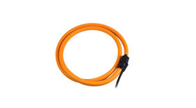
UHF (Ultra-High Frequency) Sensor
UHF partial discharge sensors detect electromagnetic emissions generated by PD activity in the frequency range of 300 MHz to 3 GHz. These are primarily applied in GIS, transformers, and cable terminations.
How It’s Applied:
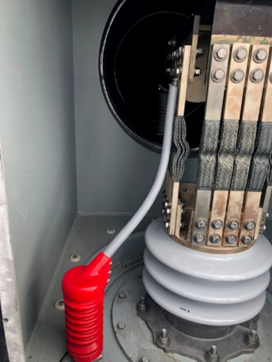
For GIS systems, UHF sensors are integrated into the GIS design via UHF drain valve sensors, couplers, or permanent UHF windows. Portable clamp-on UHF probes can be attached to inspection points or GIS enclosures during maintenance. In transformers, UHF sensors can be installed on drain valves, flanges, or specially designed UHF couplers integrated into the tank wall. They allow for online, continuous PD monitoring without interrupting equipment operation.
RFCT (Radio Frequency Current Transformer)
RFCTs detect high-frequency PD-induced current pulses traveling along the grounding cables of electrical equipment. They are typically used on transformers, GIS, cable systems, and rotating machines.
How It’s Applied:
RFCT PD sensors are installed by clamping them around the earthing or bonding cables connecting equipment enclosures to ground. As PD events induce rapid discharge currents that flow to ground, these transient currents are captured by RFCTs. During application, one or multiple RFCTs are positioned on various grounding points to identify the PD source by comparing signal amplitudes and time-of-arrival differences. They are especially effective for multi-source PD detection in substations.
Rogowski Coil
Rogowski coils are flexible, non-intrusive current sensors used for detecting high-frequency discharge currents similar to RFCTs. They are commonly applied in GIS, transformers, and high-voltage cables.
How It’s Applied:
The coil is wound around earthing conductors or cable terminations without disconnecting the system. Its flexibility allows installation in confined or awkward locations within switchgear or substations. PD monitoring systems record the pulse signals induced in the Rogowski coil, helping to locate discharge activity by analyzing current pulse shape and timing.
Coupling Capacitor Sensor
Coupling capacitors are connected to high-voltage lines to extract high-frequency PD pulses superimposed on power frequency voltage signals. They are mainly used for PD detection in GIS, HV transformers, and overhead lines.
How It’s Applied:
In GIS, coupling capacitors are permanently installed at specified measuring points. For transformers, they are connected to the transformer bushings or HV terminals to couple out PD signals. In HV overhead line systems, coupling capacitors are installed on transmission towers to monitor PD traveling along the line. They form part of an online PD measurement system by transmitting extracted signals to acquisition units for further processing.
Transformer-Specific Sensors
In transformer PD monitoring, dedicated sensors are often used for better signal acquisition without altering transformer structures.
Typical Applications:
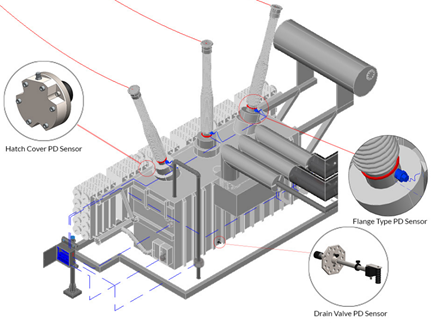
Hatch Cover PD Sensor: Installed on manhole covers to detect UHF or acoustic signals from internal PD.
Flange Type PD Sensor: Mounted on transformer flanges to couple out UHF or TEV signals.
Drain Valve PD Sensor: Attached to drain valves to extract UHF signals via the oil valve body.
These sensors are typically fixed at key points like bushings, flanges, and manholes for continuous online monitoring. Multiple sensors work together to capture PD signals and assist in locating discharge sources by comparing signal levels and arrival times.
Which sensor is used to monitor partial discharge in different applications?
Effective partial discharge monitoring depends on selecting and combining suitable sensors according to equipment structure and site conditions. By strategically deploying acoustic, electromagnetic, and current-based sensors, operators can capture diverse PD signals for reliable online detection. Integrated systems centralize these signals for real-time diagnostics, playing a key role in predictive maintenance of high-voltage assets.
Chongqing Blue Jay Technology Co., Ltd. was founded by engineers with many years of experience. Focuses on the development, production and sales of power automation monitoring products and energy metering instruments.