Application of Capacitor Reactive Power Compensation Device
1 Reactive power compensation methods commonly used in rural power grids
According to the characteristics of the reactive power load in the rural power grid and the principle of “reasonable planning, reasonable layout, decentralized compensation, and local balance” for reactive power, the rural power grid has been compensated by a compensation method that focuses on decentralized compensation and supplemented by centralized compensation. Necessary reactive power compensation.

1.1 Random compensation
Random compensation is a compensation method in which the low-voltage capacitor bank and the motor are connected in parallel, and the control and protection devices are switched on and off at the same time with the motor.
1.2 Follower compensation
Follower compensation is a compensation method in which low-voltage capacitors are connected to the secondary side of the distribution transformer through a low-voltage fuse to compensate for the no-load reactive power of the distribution transformer.
1.3 Low-voltage centralized compensation
Low-voltage centralized compensation is a way to connect the capacitor bank to the 0.4kV bus of the distribution transformer or user distribution station, and track the load change to compensate.
1.4 Centralized compensation on 10kV distribution lines
This method is to install a capacitor on the line pole to implement single-point or multi-point compensation. The single-point compensation location is selected at 2/3 away from the head end of the line, and the two-point compensation is installed at 2/5 and 4/5 away from the head end respectively.
1.5 Centralized Compensation for Substation
This method is to centrally install capacitors on the 10kV bus of the substation, and compensate according to 10%~15% of the main transformer capacity.
2 Ways to improve power factor
2.1 Improve power factor
2.1.1 Improve natural power factor
Including reasonable selection of electrical equipment, avoiding light-load operation of transformers, reasonable arrangement of technological processes, and using synchronous motors as far as possible when conditions permit.
2.1.2 Improve power factor through manual compensation
Commonly used is parallel capacitor compensation. This method is not that the higher the power factor after compensation, the better, because the compensation device consumes active power to generate reactive power. As the compensation capacity increases, its active power loss also increases, and the initial investment increases.
2.2 Parallel capacitor compensation power factor
There are three ways to compensate the power factor of parallel capacitors.
2.2.1 On-site compensation
On-site compensation is to assemble capacitors or capacitors near asynchronous motors or inductive electrical equipment, and perform reactive power compensation on-site. It is also called individual compensation or individual compensation.
2.2.2 Group compensation
Group compensation is to install capacitor banks on the high-voltage or low-voltage busbars of workshops or villages and towns terminal substations with lower power factors, which is also called decentralized compensation.
3 Troubleshooting of capacitors in operation
3.1 When handling capacitor faults, disconnect the circuit breaker and isolating switch first
After the capacitor is discharged through the discharge resistor, it is then manually discharged to discharge the remaining charge. When discharging manually, first fix the grounding end, and then use the grounding rod to touch the capacitor several times to discharge until there is no spark.
3.2 Fuel injection, explosion and fire failure
When the capacitor is sprayed with oil or exploded and catches fire, immediately disconnect the power supply and use sand or a dry fire extinguisher to extinguish the fire. In order to prevent such accidents, the specifications of a single fuse must be matched, and the cause must be carefully found after the fuse is blown.
3.3 Trip fault
If the circuit breaker of the capacitor trips and the fuse of the shunt fuse is not blown, discharge the capacitor for 3 minutes before checking the circuit breaker, current transformer, power cable, and the outside of the capacitor. If no abnormality is found, it may be caused by external faults or bus voltage fluctuations. After the inspection is normal, it can be tested. Otherwise, the protection should be further energized.
4 Application of parallel capacitor device
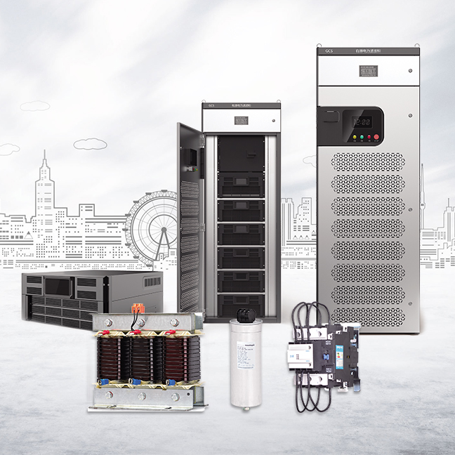
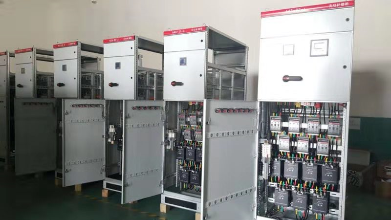
The shunt capacitor device has the characteristics of decentralized compensation and centralized compensation. It is suitable for decentralized installation and can better meet the requirements of on-site compensation; the shunt capacitor device for group switching has good reactive power regulation performance, low investment, and low energy consumption. Convenient operation and maintenance.

Parallel capacitor devices can be divided into high-voltage and low-voltage parallel capacitor devices according to the voltage points. According to the installation location, they can be divided into substation centralized compensation, distribution line compensation and local compensation devices. According to the control mode, they can be divided into automatic switching and fixed Type compensation devices are classified according to the use environment, and can be divided into indoor and outdoor types.
1 Reactive power compensation methods commonly used in rural power grids
According to the characteristics of the reactive power load in the rural power grid and the principle of “reasonable planning, reasonable layout, decentralized compensation, and local balance” for reactive power, the rural power grid has been compensated by a compensation method that focuses on decentralized compensation and supplemented by centralized compensation. Necessary reactive power compensation.

1.1 Random compensation
Random compensation is a compensation method in which the low-voltage capacitor bank and the motor are connected in parallel, and the control and protection devices are switched on and off at the same time with the motor.
1.2 Follower compensation
Follower compensation is a compensation method in which low-voltage capacitors are connected to the secondary side of the distribution transformer through a low-voltage fuse to compensate for the no-load reactive power of the distribution transformer.
1.3 Low-voltage centralized compensation
Low-voltage centralized compensation is a way to connect the capacitor bank to the 0.4kV bus of the distribution transformer or user distribution station, and track the load change to compensate.
1.4 Centralized compensation on 10kV distribution lines
This method is to install a capacitor on the line pole to implement single-point or multi-point compensation. The single-point compensation location is selected at 2/3 away from the head end of the line, and the two-point compensation is installed at 2/5 and 4/5 away from the head end respectively.
1.5 Centralized Compensation for Substation
This method is to centrally install capacitors on the 10kV bus of the substation, and compensate according to 10%~15% of the main transformer capacity.
2 Ways to improve power factor
2.1 Improve power factor
2.1.1 Improve natural power factor
Including reasonable selection of electrical equipment, avoiding light-load operation of transformers, reasonable arrangement of technological processes, and using synchronous motors as far as possible when conditions permit.
2.1.2 Improve power factor through manual compensation
Commonly used is parallel capacitor compensation. This method is not that the higher the power factor after compensation, the better, because the compensation device consumes active power to generate reactive power. As the compensation capacity increases, its active power loss also increases, and the initial investment increases.
2.2 Parallel capacitor compensation power factor
There are three ways to compensate the power factor of parallel capacitors.
2.2.1 On-site compensation
On-site compensation is to assemble capacitors or capacitors near asynchronous motors or inductive electrical equipment, and perform reactive power compensation on-site. It is also called individual compensation or individual compensation.
2.2.2 Group compensation
Group compensation is to install capacitor banks on the high-voltage or low-voltage busbars of workshops or villages and towns terminal substations with lower power factors, which is also called decentralized compensation.
3 Troubleshooting of capacitors in operation
3.1 When handling capacitor faults, disconnect the circuit breaker and isolating switch first
After the capacitor is discharged through the discharge resistor, it is then manually discharged to discharge the remaining charge. When discharging manually, first fix the grounding end, and then use the grounding rod to touch the capacitor several times to discharge until there is no spark.
3.2 Fuel injection, explosion and fire failure
When the capacitor is sprayed with oil or exploded and catches fire, immediately disconnect the power supply and use sand or a dry fire extinguisher to extinguish the fire. In order to prevent such accidents, the specifications of a single fuse must be matched, and the cause must be carefully found after the fuse is blown.
3.3 Trip fault
If the circuit breaker of the capacitor trips and the fuse of the shunt fuse is not blown, discharge the capacitor for 3 minutes before checking the circuit breaker, current transformer, power cable, and the outside of the capacitor. If no abnormality is found, it may be caused by external faults or bus voltage fluctuations. After the inspection is normal, it can be tested. Otherwise, the protection should be further energized.
4 Application of parallel capacitor device
The shunt capacitor device has the characteristics of decentralized compensation and centralized compensation. It is suitable for decentralized installation and can better meet the requirements of on-site compensation; the shunt capacitor device for group switching has good reactive power regulation performance, low investment, and low energy consumption. Convenient operation and maintenance.

Parallel capacitor devices can be divided into high-voltage and low-voltage parallel capacitor devices according to the voltage points. According to the installation location, they can be divided into substation centralized compensation, distribution line compensation and local compensation devices. According to the control mode, they can be divided into automatic switching and fixed Type compensation devices are classified according to the use environment, and can be divided into indoor and outdoor types.


