
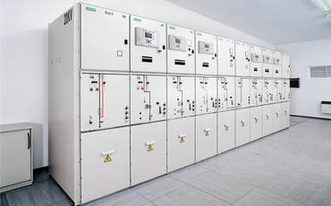
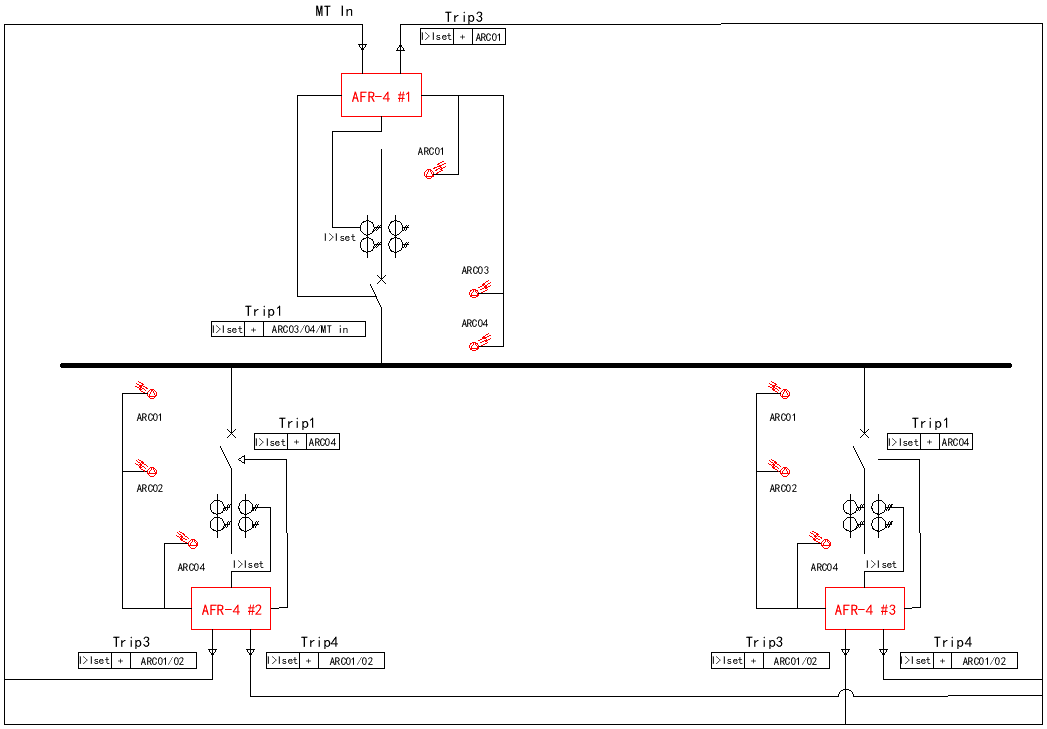
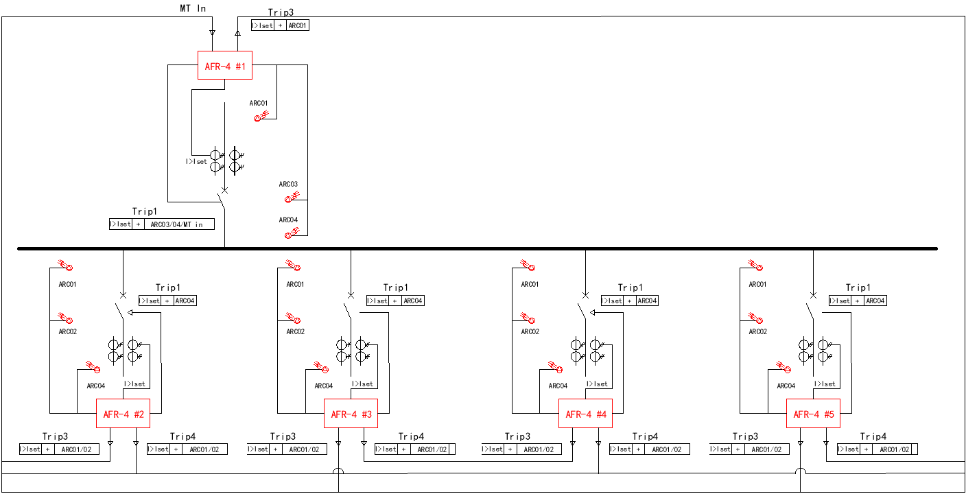
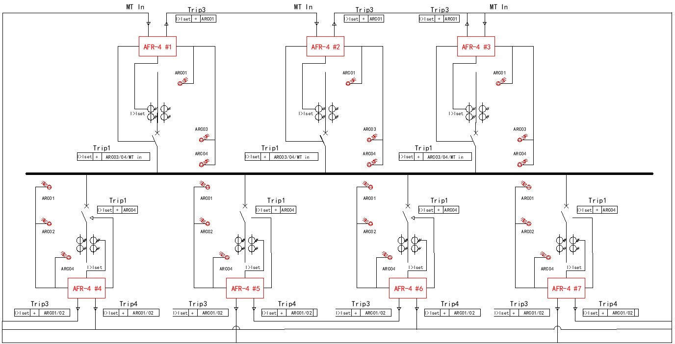
Arc Flash Protection Solution for MV Switchgear
Arc Flash Protection Solution Background and Requirements A large
A single busbar system refers to a switchgear or distribution system in which all circuits are connected to a single main busbar. The system typically has one incoming power source that feeds the main circuit breaker, which in turn connects to a continuous, unsegmented busbar.
In this configuration, the busbar is not divided into multiple sections and no bus coupler switch is used to interconnect different bus sections. Downstream of the main circuit breaker, multiple outgoing feeders — such as motors, transformers, or sub-distribution panels — can be connected to supply power to various loads.
With technological advancement, modern single busbar systems may also feature dual power inputs (dual incomer configuration), while still maintaining a single continuous busbar structure.
| Type | Main Power Input | Busbar Structure | Reliability | Typical Application |
| Single Incomer Single Busbar System | One | Single continuous bus | Basic | Small power distribution panels, commercial buildings |
| Dual Incomer Single Busbar System | Two | Single continuous bus | Higher, with backup source | Industrial facilities, substations with redundancy |
In a single busbar configuration, the installation of an arc flash relay is primarily aimed at protecting personnel and minimizing equipment damage, rather than improving system reliability — since any trip at the main breaker will cause a total shutdown of the system.
Arc-flash sensors are usually installed in the main incomer panel and feeder breaker compartments where the busbar and cable terminations are located. When an arc fault occurs, regardless of whether it happens at the main breaker or in one of the feeder sections, the arc-flash relay immediately trips the upstream main breaker. This action rapidly removes the fault energy source, limiting both equipment damage and injury risks to operators.
Compact or Small-Scale Power Distribution Systems
Small factories, commercial buildings’ low-voltage switchboards, elevator machine room distribution boxes, and auxiliary power systems in small substations typically use single-section busbar systems. Although these systems are small in scale, short-circuit currents can still be very large. In the event of an arc flash, it can be dangerous for maintenance personnel. Therefore, arc flash protection relays are needed to quickly cut off the power supply and reduce the probability of injury.
Areas Requiring Frequent Live-Line Operation or Maintenance
Old or Upgraded Switchgear
Old upgraded switchgear/distribution cabinets are prone to arc flash due to insulation aging, mechanical component wear, and improper maintenance. Installing arc flash protection relays in these devices can improve equipment and personnel safety without replacing the switchgear.
Systems under high short-circuit current environments
A single busbar section may be connected to a transformer or power source with a large short-circuit capacity. Common locations include distribution rooms near main power substations and main switches in large industrial facilities. The higher the short-circuit current in these areas, the higher the energy generated by the arc flash. Installing arc flash protection relays can quickly prevent arc flash accidents.
The main difference between different types of single bus bar systems lies in the number of downstream feeder (outgoing) circuit breakers.
The configuration of arc flash protection relays (AFR) also varies depending on the load quantity and system structure.
Arc flash relay configuration for dual power supply – single bus system with one load
System Overview: Bus supplied by Power A (main) and Power B (backup) via a bus tie or automatic transfer switch, feeding one load branch.
Purpose of arc flash protection: detect arc faults on the bus or load branch, rapidly trip breakers, and ensure load and system safety.
Arc Flash Relay Installation Plan – 3 Units of AFR-4
| Relay | Monitoring Scope | Function |
| AFR‑4 #1 | Bus incoming line A + main bus section | Monitors main bus and primary source; triggers bus breaker or bus tie trip |
| AFR‑4 #2 | Bus incoming line B + main bus section | Monitors backup source; can trip independently or in coordination with #1 |
| AFR‑4 #3 | Load branch + bus end | Monitors load branch and bus end; triggers load breaker trip |
Notes:
Each AFR‑4 arc flash relay has 4 channels; channel allocation can fully cover incoming lines, bus, and critical branch points.
Current transformers (CTs) are recommended on each monitored line/section for combined current + arc detection.
Relay outputs can be configured to trip the bus breaker, bus tie, or branch breaker according to protection strategy.
Arc flash relay configuration for single power supply – single bus system with two loads
System Description: A single busbar trunk line originates from a single power source; two load branches branch off from this busbar (Branch 1 and Branch 2).
The structure is relatively simple, but the more load branches there are, the more arc fault propagation paths there are, requiring coverage of detection points.
Arc Flash Relay Installation Plan – 3 Units of AFR-4
| Relay | Monitoring Area | Function Description |
| AFR-4 #1 | Bus section | Monitors the entire busbar section for arc flash and trips the main circuit breaker. |
| AFR-4 #2 | Feeder 1 (incoming) | Monitors feeder 1 for arc flash faults and trips the feeder 1 circuit breaker. |
| AFR-4 #3 | Feeder 2 (incoming) | Monitors feeder 2 for arc flash faults and trips the feeder 2 circuit breaker. |
Notes:
Bus relays independently monitor the main busbar, enabling rapid handling of busbar faults.
Each branch relay independently monitors its load branch, allowing for partial tripping and minimizing impact on busbar power supply.
Current transformers (CTs) can be installed at the busbar inlet or before branch circuit breakers, supporting combined triggering.
Arc flash relay configuration for single power supply – single bus system + four loads
System Description: A main busbar branches out into four loads branches (Branches 1-4). This structure results in a large number of loads, long branch paths, and potentially more complex faults.
Recommended Configuration: 5 Units of AFR-4
| Relay No. | Installation Location | Monitoring Area | Trip Target |
| AFR-4 #1 | Bus section | Main busbar zone | Trip main circuit breaker |
| AFR-4 #2 | Feeder 1 | Load branch 1 | Trip feeder 1 breaker |
| AFR-4 #3 | Feeder 2 | Load branch 2 | Trip feeder 2 breaker |
| AFR-4 #4 | Feeder 3 | Load branch 3 | Trip feeder 3 breaker |
| AFR-4 #5 | Feeder 4 | Load branch 4 | Trip feeder 4 breaker |
Notes:
Bus protection: AFR‑4 #1 independently monitors the entire main busbar section. In case of an arc fault on the bus, it trips the main circuit breaker, preventing propagation to all branches.
Feeder-level protection: Each feeder relay (AFR‑4 #2–#5) monitors its dedicated load branch. Arc faults on a branch will only trip the corresponding feeder breaker, minimizing impact on other feeders and maintaining overall supply continuity.
Current transformer (CT) placement: CTs can be installed at the busbar inlet or before each branch breaker to enable combined light + current detection and improve reliability of trip logic.
Multi-power single-bus system configuration (Example three power supply – single bus system + four loads)
System Description: This structure involves multiple (two or more) independent power supply lines (e.g., power supply A, power supply B, power supply C, etc.) converging onto a single bus, which then branches off into multiple load branches.
Features: Multiple power supply paths, high redundancy, the bus is extremely critical, and the impact of a fault is widespread.
Recommended Configuration: 7 Units of AFR-4
| Relay | Installation Location | Monitoring Area | Trip Target |
| AFR-4 #1 | Bus A section | Monitors arc faults on bus section A | Trips power supply A breaker |
| AFR-4 #2 | Bus B section | Monitors arc faults on bus section B | Trips power supply B breaker |
| AFR-4 #3 | Bus C section | Monitors arc faults on bus section C | Trips power supply C breaker |
| AFR-4 #4 | Feeder 1 | Monitors feeder 1 branch | Trips feeder 1 breaker |
| AFR-4 #5 | Feeder 2 | Monitors feeder 2 branch | Trips feeder 2 breaker |
| AFR-4 #6 | Feeder 3 | Monitors feeder 3 branch | Trips feeder 3 breaker |
| AFR-4 #7 | Feeder 4 | Monitors feeder 4 branch | Trips feeder 4 breaker |
Notes:
Bus protection zoning: Each bus relay (AFR-4 #1–#3) independently monitors its corresponding power-fed bus section (A, B, C). In the event of an arc fault, the affected relay trips only its associated power supply breaker, keeping other sources in service.
Feeder-level isolation: Each feeder relay (AFR-4 #4–#7) monitors its dedicated load branch. When an arc fault occurs on a branch, only the relevant feeder breaker opens, minimizing disturbance to the rest of the system.
Current and power source arrangement: CT inputs can be installed on each power supply incomer or near the feeder breakers for combined light + current detection logic. All AFR-4 units can share a common DC auxiliary power supply.
In summary, regardless of the number of downstream load branches in a single-bus system—whether one, two, or four—any arc flash event detected by the AFR-4 relay will trigger the main circuit breaker. This rapid response ensures that the bus and all connected loads are immediately isolated from the fault, effectively protecting personnel and equipment.

Arc Flash Protection Solution Background and Requirements A large

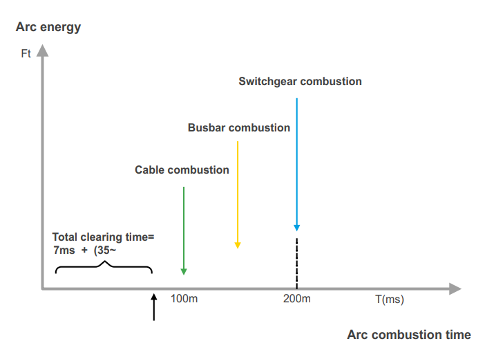
What is arc flash incident energy? Arc flash incident

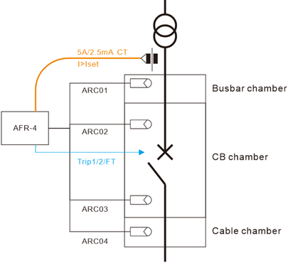
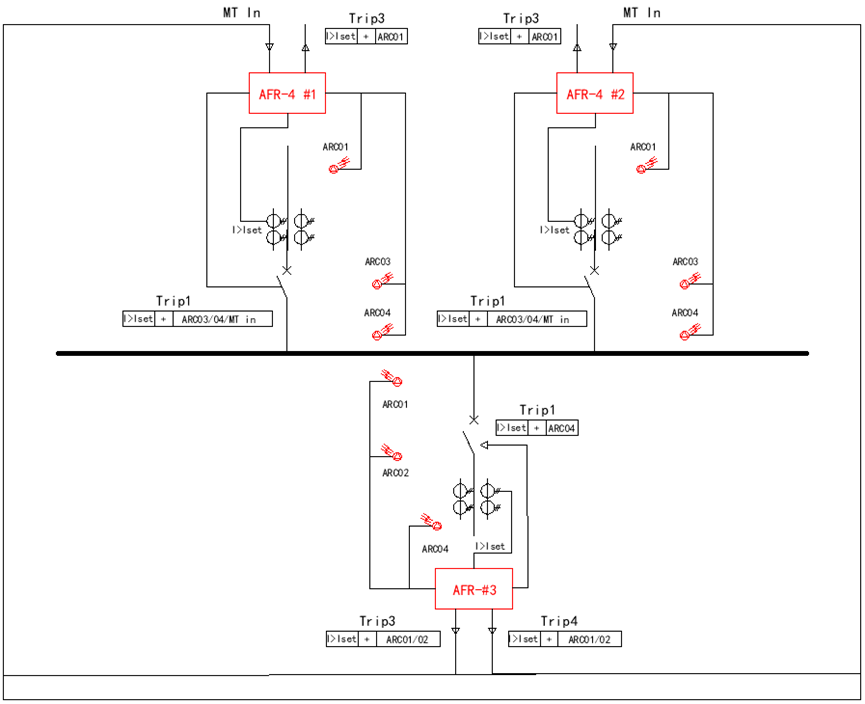
Abstract: This article will introduce you Switchgear arc flash
