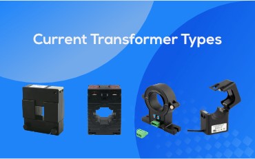
What Is the Type of Current Transformer?
As for the type of current transformer (CT), there
Current transformer installation is very important to ensure accurate and safe operation. This guide will introduce the types and attentions of current transformer installation.
Before installation, it’s vital to choose the right-sized CT for your application. Proper sizing ensures accurate current measurement. To determine the appropriate CT size, consider factors such as the maximum current to be measured and the CT’s ratio. Consulting manufacturer guidelines and electrical engineers can help with this.
Wire polarity is essential for accurate measurement. Make sure that the direction of the current flow matches the CT’s markings and wiring diagrams provided by the manufacturer. Incorrect polarity can lead to inaccurate readings.
One of the most critical aspects of CT installation is the direction of current flow. Proper understanding of current direction ensures accurate energy metering:
Forward Metering (P1-P2 Direction): When the CT is installed with the current flowing from P1 (source) to P2 (load), it records the energy consumption from the source to the load. This is considered the normal, or positive, direction of metering.
Reverse Metering (P2-P1 Direction): If the current flows in the opposite direction (P2 to P1), the energy meter will register negative values, indicating reverse energy flow, such as when power is fed back into the grid or from a load to a source.
If negative values are recorded, it means that the meter is measuring energy flowing from the load back to the source. To correct this and measure forward energy flow (source to load), there are two possible methods:
Method 1: Reinstall the CT so that the current flows from P1 to P2. By reversing the direction of the CT installation, the energy meter will begin recording the forward energy flow in the correct direction.
Method 2: If the CT is already installed in reverse (P2-P1 direction), swap the connections of S1 and S2. Connect S1 (red wire) to the negative terminal of the meter and S2 (black wire) to the positive terminal. This will reverse the wiring and correct the direction of current flow, allowing accurate measurement of forward energy.
Multi-Channel Meters and Reverse Energy Flow
In industrial applications, multi-channel meters are often used to monitor multiple circuits simultaneously. In many cases, some channels measure the forward consumption of energy from the source to the load. However, certain applications, such as uninterruptible power supplies (UPS) and photovoltaic (PV) systems, may involve both energy consumption and generation.
In such cases, reverse energy flow might occur, where energy is fed back to the grid or shared between different components of the system. Some channels may display negative values, indicating the return of energy to the source, while others will show positive values reflecting energy consumption from the source to the load.
The orientation and polarity of the CT matter significantly. Ensure that the CT is properly oriented concerning the conductor it’s measuring. Proper alignment is essential for accurate readings and safety.
In a typical CT setup, the S1 (red wire) of the CT is connected to the positive terminal of the current input on the energy meter, while the S2 (black wire) is connected to the negative terminal of the current input. This standard wiring configuration ensures that the CT operates as intended, measuring the current in the correct direction.
Place the CT around the correct conductor or cable. It should encircle the conductor without any obstruction or air gaps. Proper placement ensures that the CT can accurately measure the current flowing through the conductor.
Pay close attention to the lead wires of the CT. Ensure they are in good condition, without any visible damage or wear. Damaged lead wires can affect the CT’s performance and safety.
Finally, connect the CT lead wires to the input terminals of the monitoring or measuring equipment. Follow the manufacturer’s guidelines and wiring diagrams for proper connections. Secure the connections to prevent any loose wires or accidental disconnections.
In conclusion, correct current transformer installation is essential for accurate current measurement and the overall safety of your electrical system. You should always consult the manufacturer’s instructions and seek professional assistance if needed. By following these steps, you can ensure the proper functioning of your CT and maintain the integrity of your electrical measurements.
As for the type of current transformer (CT), there
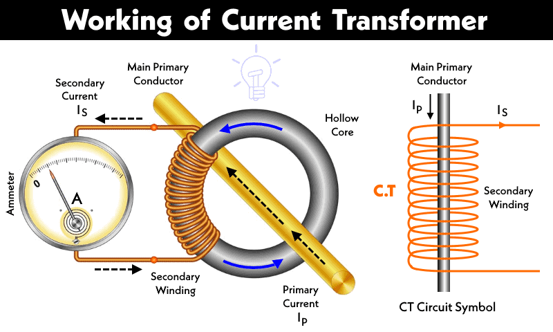
A current transformer is a commonly used power measurement equipment.
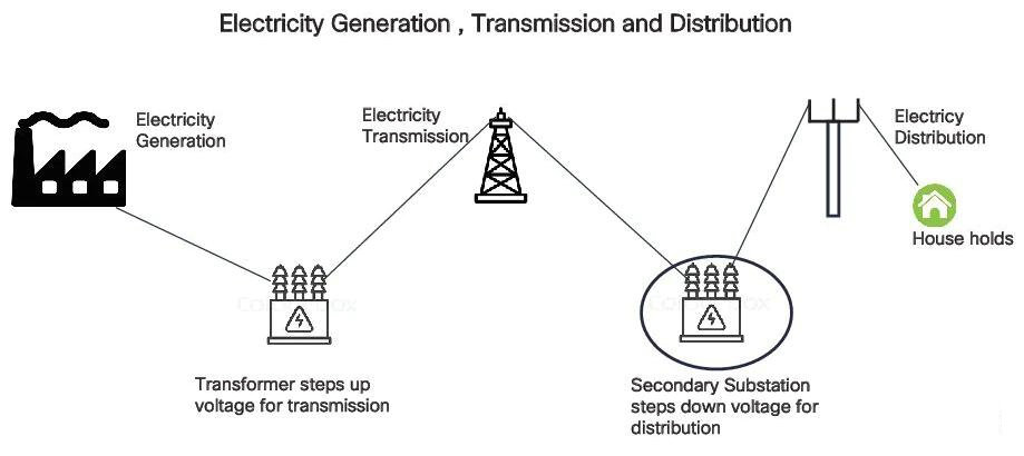
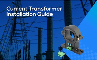
1 Introduction In the process of substation construction at