
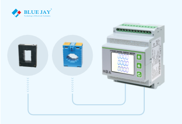

Do you know how to connect CT to energy meter? Connecting Current Transformers (CTs) with energy meters is a critical step in accurately measuring and monitoring electrical currents in various applications, from residential to industrial settings. This article will introduce how to connect CT to energy meter step by step.
There are 7 steps for how to connect CT to energy meter in the following:
Before connecting CTs to an energy meter, it is crucial to have a clear understanding of CTs. CTs are devices designed to measure alternating current (AC) by producing a proportional current in its secondary winding for a given current in the primary winding. It is essential to choose the appropriate CT based on the characteristics of the electrical system it will monitor.
Recommended current transformer

DP-X Split Core Current Transformer
This CT is available for primary current from 5A to 5000A.
2 built-in fixing methods: Panel/Busbar
Revenue grade accuracy meets IEC61000-1 class 0.5 / 1.0
Withstand Voltage: 3000Vac @ 2mA / 1min / 50Hz
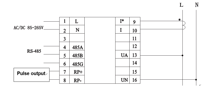
Take the DEM-7M3D (19D-37D) 3 Phase Din Rail Energy Meter of Blue Jay technology as an example.
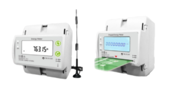
Choose a CT that matches the specifications of the energy meter and the electrical system. Consider factors such as the primary current rating, accuracy class, and burden, ensuring compatibility with the metering equipment.
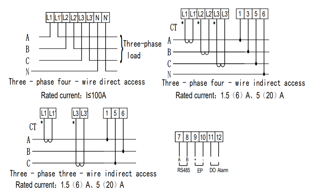
Wiring Notes:
Must choose a suitable cable size to connect, please refer to the meter measurement range and actual load condition.
The communication wire must use a shielded twisted pair.
Communication line RS485+, RS485- cannot be reversed.
If need long-distance communication to the host, must parallel connect 100~120ohms resistor in both terminals of the host to slave.
In the 9600 baud rate, the cable length should be less than 1200 meters.
Follow these general steps for installing CTs:
Ensure power to the circuit is turned off before installation.
Open the electrical panel or junction box where the CTs will be installed.
Securely mount the CTs around the conductor carrying the current to be measured, ensuring proper alignment and connection.
Connect the CTs to the energy meter using appropriate wiring techniques:
Connect the CT secondary leads to the corresponding terminals on the energy meter.
Observe proper polarity, ensuring that the current direction aligns with the marked direction on the CT.
Warnings:
If power = -0.01 is shown for any of the phases and voltage and current are not zero for this phase, check out the following points:
– Assure that A, B, and C phases coincide in voltage and current.
– Correct polarity? Flip the current transformer that is positioned at this stage.
Configure the energy meter to recognize and interpret the signals from the CTs:
Set the primary and secondary current values in the energy meter’s settings menu based on the CT specifications.
Verify that the energy meter is configured for the appropriate CT ratio.
Before finalizing the connection, conduct thorough testing and calibration.
Once satisfied with the connections and calibration, seal the CTs and secure all wiring to prevent tampering or accidental disconnection.
Connecting CTs with energy meters is a crucial aspect of electrical metering and monitoring. By following these steps carefully, you can ensure a reliable and accurate measurement of electrical currents, contributing to efficient energy management and billing accuracy. Regular maintenance and periodic checks are recommended to guarantee the ongoing accuracy of the CT and energy metering system. In a word, we hope this guide about how to connect CT to energy meter is helpful for you.
Recommended CT Energy Meter
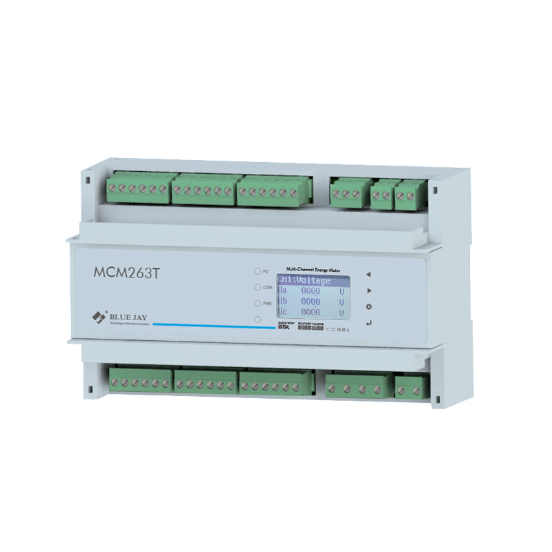
MCM263T 6 Channel CT Energy Meter
The MCM263T is a 6-channel energy meter, installed with CT.
Up to 6 or 18 branch circuit metering
Multi-communication Port & Multi-protocol Supported
Mult-combination of Input/Output

The difference between a CT energy meter and a

