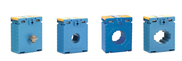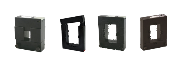
How to select a current transformer correctly?
1. What is a current transformer? A current transformer

A current transformer is a device used to measure current by sensing it and converting it into a measurable signal. Current transformers are commonly used in applications such as energy measurement, current monitoring, current protection, and control. The basic principle is to use electromagnetic induction to transfer the current on the high-current wire (main wire) to the secondary winding through magnetic field induction, thereby achieving current measurement.
Its working principle is based on Faraday’s law of electromagnetic induction. The magnetic field generated around the main wire (the wire through which the measured current passes) induces the current in the auxiliary secondary winding, thereby achieving the measurement of current.

The following is a detailed explanation of how a current transformer works:
Main wire: The main wire of a current transformer refers to the wire through which the measured current passes. Typically, the main conductor is a wire that passes through the center hole of the current transformer.
Secondary Winding: A current transformer contains a secondary winding, usually wound around the main conductor. This secondary winding is usually wrapped in insulating material to electrically isolate it from the primary conductor.
Magnetic Field Induction: When electric current passes through the main conductor, it creates a magnetic field. This magnetic field will pass through the secondary winding, and according to Faraday’s law of electromagnetic induction, changes in the magnetic field will induce an electromotive force in the secondary winding.
Electromotive force and secondary current: Due to the existence of electromotive force, a certain current will be generated in the secondary winding. This current is proportional to the current on the primary conductor, so by measuring the secondary current, the magnitude of the current on the primary conductor can be determined.
Transformation Ratio: The transformer ratio between the main conductor current and the secondary current is considered in the design of the current transformer. The transformation ratio determines the sensitivity and measurement range of the current transformer.
Output signal: The secondary current passes through a measuring device, such as an ammeter, current transmitter or other current measuring equipment, and outputs a corresponding signal of the measured current.
Generally speaking, the current transformer achieves the measurement of current by inducing the magnetic field generated by the current being measured, thereby generating current in the secondary winding. The non-contact nature of this measurement method allows current transformers to safely and accurately measure high currents while avoiding the safety hazards of direct connection to main conductors.
3.1. Closed loop current transformer

Definition: A closed-loop current transformer is a current transformer that controls the relationship between the output current and the input current through a feedback loop (closed loop). This type of transformer continuously adjusts the current in the secondary winding to maintain a precise ratio of the output current to the current on the main conductor.
Advantage:
High accuracy and stability: Closed-loop control makes the transformer more sensitive to changes in the external environment, thereby providing high-precision and stable current measurement.
Low drift: Ability to reduce drift effects and ensure measurement accuracy is maintained over long periods of use.
3.2. Open loop current transformer

Definition: An open-loop current transformer is a current transformer that does not adjust the relationship between the output current and the input current through a feedback loop. The proportional relationship between its output current and the current on the main line is fixed during design.
Advantage:
Relatively simple and economical: Open-loop current transformers are generally simpler and more economical because they do not require a closed-loop control system.
Withstand external magnetic field interference: Compared with closed-loop transformers, it has less impact on external magnetic field interference.

Definition: Hall Effect Current Transformer is a sensor that uses the Hall effect to measure current. The Hall effect refers to the phenomenon that when a conductor is energized, a Hall element placed near it generates a voltage difference. The voltage difference is proportional to the intensity of the current.
Advantage:
Accuracy: Hall CT can provide high-precision current measurement, especially in the low current measurement range.
Wide frequency band: Hall CT has a wide adaptability range to frequency and can be used in AC and DC systems.
Low energy consumption: Hall CTs generally have low energy consumption and are suitable for applications requiring long operation times.
3.4. Micro current transformer

Definition: A micro current transformer is a smaller-size current transformer usually designed for applications in tight spaces.
Advantage:
Compact size: suitable for scenarios with limited space, such as small electronic equipment.
Lightweight design: suitable for occasions where the weight of the equipment is limited.
When matching primary conductor sizes, the conductor geometry, cross-sectional area, material conductivity, and number of conductors should be considered. Make sure the current transformer through-hole size can accommodate the main conductor to provide accurate current measurement.
The transformation ratio represents the ratio between the input current and the output signal of the current transformer. Detailed performance analysis is required when selecting a transformation ratio, taking factors such as nonlinearity, phase error, and temperature dependence into consideration. Ensure that the transformation ratio meets the accuracy and sensitivity requirements of the application.
When selecting the rated current, in addition to considering the maximum value of the current being measured, the non-sinusoidality of the current waveform in the system must also be considered to ensure accuracy under non-ideal conditions.
The maximum power load that a current transformer can withstand. When selecting the rated power, it is necessary to understand the load conditions in detail and consider the performance of the current transformer under non-ideal loads to ensure that it can work stably under various load conditions.
Rated operating frequency of current transformer. In power systems, 50Hz or 60Hz current transformers are usually used. Make sure to select the applicable rated frequency to ensure that the current transformer works properly in the system.
Accuracy class is a measure of the accuracy of current transformer measurements. When selecting an accuracy level, a thorough understanding of the sources of measurement errors, such as temperature, load, magnetic fields, etc., is required to determine the appropriate accuracy level.
Whether the current transformer complies with relevant certification standards, such as ISO, CE, etc. Choose current transformers that meet international and regional certification standards to ensure their quality, safety and compliance. Certification can include product safety certification, environmental certification, etc.
When selecting a current transformer, the above factors require in-depth analysis and may require close cooperation with power system engineers and instrumentation experts to ensure that the selected current transformer fully meets the system requirements.

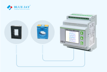
The compatibility between the current transformer (CT) and the energy meter is a critical factor in ensuring accurate current measurement and precise energy metering. The following factors should be taken into consideration.
Rated Current Matching: Ensure that the rated current of the CT matches the rated current range of the energy meter. Typical energy meters have rated currents of 5A or 1A, so choose a CT with the corresponding rated current.
Consistency in Transformation Ratio: The transformation ratio of the CT should be consistent with the input requirements of the energy meter, ensuring correct current measurement and accurate power calculation. Check the transformation ratio relationship between the CT and the energy meter and ensure their consistency.
Phase Relationship: The phase relationship of the CT should match that of the energy meter. Inconsistencies in phase relationships may lead to errors in power calculations, so ensure that phase errors are within acceptable limits.
Load Characteristic Matching: Understand the load requirements of the energy meter for the CT. Choose a CT with performance characteristics that match the load conditions, ensuring accurate measurements under various load conditions.
Frequency Consistency: Ensure that both the CT and the energy meter can operate at the same rated frequency. Typically, 50Hz or 60Hz is used in power systems, so consistency in operating frequency is crucial.
The output of the CT refers to the current signal generated by its secondary winding, which is input to the energy meter for measurement and metering. The following factors should be taken into consideration.
Output Calibration: Understand the output calibration of the CT, i.e., the proportionality between the secondary current and the primary line current. This is related to the input requirements and calibration of the energy meter, ensuring accurate output at calibration points.
Secondary Load: The energy meter should be able to accommodate the secondary load requirements of the CT. Understand the tolerance of the energy meter for the secondary current of the CT, ensuring the stability of the system’s performance.
Output Type: Understand the output type of the CT, whether it is analog output (current or voltage signal) or digital output. Ensure that the output type of the CT matches the input interface of the energy meter.
Linearity and Accuracy: Ensure that the CT’s output remains linear across the entire measurement range and has the required accuracy. This is crucial for accurate energy measurement and metering.
Impedance Matching: The energy meter should have sufficient input impedance to ensure proper loading of the CT’s secondary winding and prevent distortion of the output signal.
In conclusion, when selecting a CT, careful consideration of its compatibility with the energy meter is necessary. Ensure the accuracy, linearity, and adaptability of the output signal to meet the requirements of the energy metering system. This often requires a detailed understanding of the technical specifications of both the energy meter and the CT to ensure their synergy in practical applications.

1. What is a current transformer? A current transformer

Do you know how to connect CT to energy

Abstract: Excepts for how to set CT Ratio in


