Four insulation monitoring device circuit Solutions
Insulation monitoring device circuit solutions are essential for ensuring
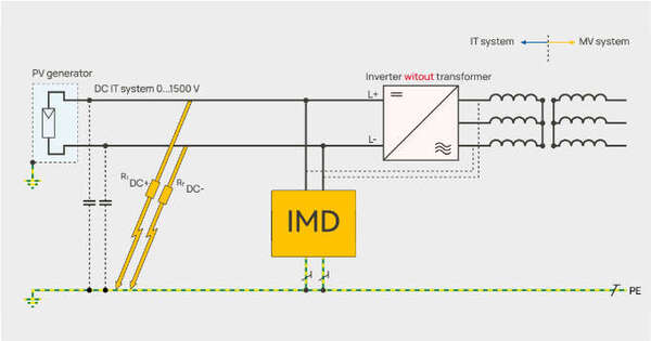

Insulation monitoring device circuit solutions are essential for ensuring
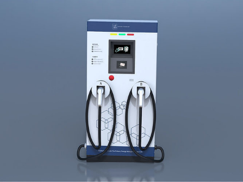
Want to know about a dual ev charger insulation
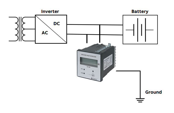
Battery energy storage systems (BESS) are typically ungrounded systems,