
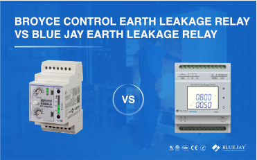
Broyce Control Earth Leakage Relay VS Blue Jay Earth Leakage Relay
Are you still unsure how to choose between the
Leakage current in a subway station’s power distribution system is a critical electrical safety indicator. It refers to the amount of current that should not flow under normal operating conditions but instead flows through insulation or stray capacitance to the ground or other non-charged conductors. Effectively controlling and monitoring leakage current is crucial for subway stations, as it directly impacts the safety of passengers and staff, as well as the proper operation of equipment. This article will introduce the subway station power distribution system from definition, components, Load classification, leakage current reasons, and leakage current protection solutions.
The power distribution system in a subway station is a core component of urban rail transit infrastructure. It’s responsible for converting high-voltage electricity into low-voltage power to run various equipment throughout the subway station. This subway distribution system is the station’s lifeline, ensuring that all electromechanical equipment, including lighting, ventilation, air conditioning, escalators, ticketing machines, security systems, and communication signals, functions properly. Ultimately, the metro’s power distribution system has a direct impact on the station’s operational efficiency and passenger safety.
A typical subway station power distribution system consists of the following main components:
High-voltage incoming power cabinet: High-voltage cables (typically 10 kV) from the city grid or a dedicated rail transit substation first enter the station’s high-voltage switchgear. This cabinet contains equipment such as circuit breakers, disconnectors, and instrument transformers for controlling and protecting the high-voltage circuits.
Step-down transformer: This transformer steps down the high-voltage power to the low-voltage power required by station equipment, such as 400 V or 230 V. Typically, subway stations are equipped with two or more transformers for backup to improve power supply reliability.
Low-voltage distribution cabinet: Also known as the low-voltage main switchgear, this cabinet receives the low-voltage power output from the transformer. It distributes this power to various secondary or tertiary distribution boxes via equipment such as main circuit breakers, busbars, and tie switches.
Distribution boxes/cabinets: These are distribution nodes located throughout the station, such as the ventilation and air conditioning machine room, lighting control room, and escalator room. Each distribution box contains circuit breakers, fuses, and leakage current devices, which control and protect the electromechanical equipment and lighting circuits they serve.
Emergency Generator: When all external power sources are lost, a diesel generator or uninterruptible power supply (UPS) system activates to provide backup power for primary loads within the station, such as emergency lighting, firefighting equipment, and critical communications equipment.
Uninterruptible Power Supply (UPS): Provides high-quality, uninterrupted power to equipment such as computers, communications equipment, and signaling systems that cannot tolerate momentary power interruptions.
The electrical loads for electromechanical equipment and lighting at subway stations are divided into three tiers based on their importance to ensure power supply reliability.
Level 1 loads: Core loads are supplied by dual power sources with automatic switching to ensure power continuity.
Level 2 loads: Direct power is supplied from the busbars of the step-down substation or environmental control room.
Level 3 loads: The most direct power supply method is achieved, with single-circuit power cables extending from the Level 3 load busbar section to the equipment.
The root cause of leakage current in subway station power distribution systems is that the current flowing from the power source fails to return in the intended path. Specifically, these issues can occur:
When switching between dual power sources, the neutral (N) wire is connected in parallel, disrupting the current return path.
Multiple grounding points in the TN-S system provide additional return paths.
Improper wiring during construction and installation, such as incorrectly connecting the N and PE wires, can lead to equipment damage, malfunctioning protective devices, and even fire and electric shock risks.
Disconnecting the neutral line (N line): Switches used for dual power switching (such as ATS, contactors, and circuit breakers) must be able to simultaneously disconnect both the live and neutral lines. Single-phase circuits should use two-pole switches, while three-phase circuits should use four-pole switches.
Avoiding parallel neutral connections: When using single-busbar sectionalized wiring, the bus tie switch should use a four-pole circuit breaker. Emergency lighting power supply circuits used for switching power modes should also use four-pole switches to ensure the independence of the neutral lines of each circuit and prevent mixed connections.
Adhering to TN-S system principles: TN-S systems must strictly adhere to the single-point grounding principle, ensuring that the N and PE lines remain independent after being separated from the grounding point and are not reconnected. Furthermore, the phase and neutral lines of the same circuit should be laid parallel to each other, and the neutral line should not be shared.
Enhancing construction and commissioning: Before power is applied, the distribution system must undergo insulation and leakage current testing to ensure that the system is in good condition. During the power-on commissioning phase, in addition to routine functional tests, the zero-sequence current, residual current, and harmonic content of the circuit must also be monitored to ensure safe and reliable operation of the system.
Leakage current protection relays can quickly operate when leakage current exceeds a set threshold, isolating the fault and preventing the incident from escalating.
This is the most direct and effective solution for protecting personnel. In the subway station power distribution system, terminal distribution circuits are frequently exposed to human contact, such as lighting circuits, maintenance socket circuits, and escalator control circuits.
Earth leakage relay selection: Choose Blue Jay high-sensitivity (≤30mA) leakage current protection relays. These earth leakage relays can operate at extremely low leakage currents. In the event of an electric shock, they typically shut off power within 0.1 seconds, far faster than the current-time threshold a person can withstand.
Implementation: Install one or more high-sensitivity leakage current protection relays on the incoming line side of each terminal distribution box (such as a lighting box or socket box). This way, even if a leakage occurs in a circuit, it only affects that circuit and does not affect the power supply to other areas.
This is a comprehensive solution for the entire distribution system, ensuring both safety and power continuity.
First-Level Protection (Main Switch Side):
Leakage Current Relay Selection: Install a low-sensitivity (100–300 mA) leakage current protection relay with a time delay function on the main incoming line and the main distribution cabinet.
Purpose: Primarily serves as backup protection, clearing faults when terminal protection fails to operate. It also monitors the overall system leakage current level and provides early warning. The time delay function prevents false tripping before terminal protection operates, ensuring selectivity.
Second-Level Protection (Branch Circuit):
Earth Leakage Current Relay Selection: Install a medium-sensitivity (50–100 mA) leakage current protection relay on branch circuits for critical equipment (such as pumps, escalators, ventilation systems, and lighting systems).
Purpose: Provides a higher level of protection without compromising terminal protection selectivity. When a branch circuit leaks, it prioritizes shutting down that circuit, minimizing the impact of the fault.
Third-Level Protection (End Circuit):
Leakage Current Relay Selection: As previously mentioned, high-sensitivity (≤30mA) fast-acting leakage current relays are installed in all potentially accessible end circuits for direct personal protection.
This tiered leakage current protection scheme utilizes leakage current relays with varying sensitivities and operating times to work together, forming a tight protection network. When a leakage fault occurs, the protector closest to the fault point and with the highest sensitivity will activate first, minimizing the impact of the fault and ensuring the safety and operational reliability of the subway station’s power distribution system.
Are you still unsure how to choose between the
An earth leakage relay can protect humans and equipment
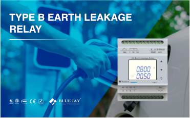
Type B earth leakage relay is a Type B