| Supply voltage |
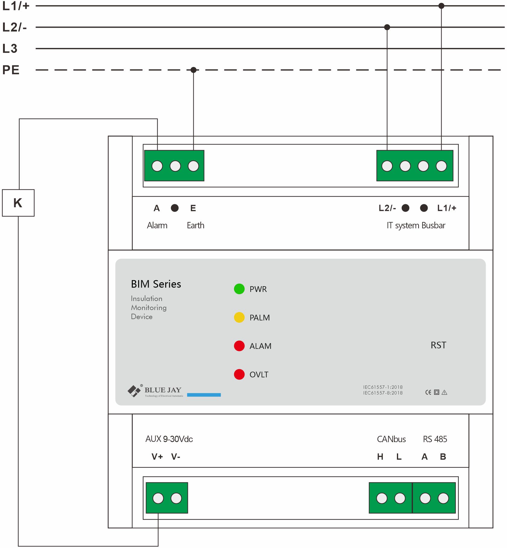
| Power supply |
9~30Vdc, power consumption ≤ 2W |
| Frequency range |
40~65Hz |
| Monitored IT system |
| Nominal system voltage |
0…1000 Vac/dc |
| Frequency range |
40~65Hz |
| Insulation resistance |
| Insulation resistance
measurement range |
0~50MΩ |
| Insulation resistance
measurement accuracy |
0~100 KΩ, CY≤ 2μF, Bus voltage stability: ±12 KΩ
100 kΩ~1 MΩ, CY≤ 2μF, Bus voltage stability: ±10 %
1 MΩ~50 MΩ, CY =0μF, Bus voltage stability: ±10 % |
| IR response time |
IRz≥ 500 kΩ, CY = 0μF, bus voltage stabilizes for 4s
IRz < 500 kΩ, CY = 0μF, bus voltage stabilizes for 5s
IRz = 1MΩ, CY = 1μF, bus voltage stabilizes for 8s
IRz = 1MΩ, CY = 2μF, bus voltage stabilizes for 12s |
| DC equivalent
internal resistance |
Power on: 10.2 MΩ |
| High voltage input internal resistance |
| When powered on
(internal high-voltage relay closed) |
Positive and negative poles to earth: 5.1 MΩ respectively |
| When powered off or not operating (internal high-voltage relay opened) |
Positive and negative poles to earth: > 500 MΩ |
| Measuring circuit |
| Injection measuring voltage |
±15V |
| Injection measuring current |
<110 µA |
| Injection pulse signal frequency |
Self-adaptive, depending on the Y-capacitance (CY) value and insulation resistance value. |
| Permissible system
leakage capacitance |
≤4μF |
| Alarm output (optocoupler) |
| Max. switching current |
>100mA |
| Max. withstand voltage |
12Vdc |
| Pre-alarm threshold |
Default 1000Ω, 0-5000Ω adjustable,
But must< alarm value |
| Alarm threshold |
Default 500Ω, 0-5000Ω adjustable |
| Overvoltage detection |
0-1000V |
| Safety |
| High to low voltage
withstanding voltage |
3 500 Vd.c. 2 500 Va.c.(rms) |
| CAN to high voltage
withstanding voltage |
3 500 Vd.c. 2 500 Va.c.(rms) |
| Communication |
| RS485 interface |
Modbus RTU protocol |
| Canbus interface |
Custom protocol |
| Environment |
| Working temperature |
– 40°C ~85°C |
| Storage temperature |
– 40°C ~85°C, humidity: 5~95%RH |
| Others |
| Standards |
EC 61557-1:2018 and IEC 61557-8:2018 |
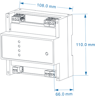
| Installation method |
Standard 35mm Din-rail mounting |
| Dimension |
W*H*D: 108*110*66mm |
")
")
")
")