What Is Insulation Monitoring Device Working Principle?
By bluejay | Company News
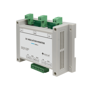
When it comes to the insulation monitoring device working principle, three primary monitoring principles are currently used: balanced bridge, unbalanced bridge, and signal injection. In this article, we’ll break down how DC insulation monitoring device works with practical applications.
Insulation Monitoring Device Working Princple Overview
1. Balanced Bridge working Principle for IMD
DC insulation monitoring device using a balanced bridge works like a precise seesaw. It uses a Wheatstone bridge to compare the insulation resistance between the DC system’s positive and negative poles to ground against known resistors. When insulation is good, the bridge is balanced, and the output voltage is near zero. If insulation fails, the resistance becomes unbalanced, the voltage changes and the insulation monitoring device triggers an alarm, safeguarding the DC system. If you want to find insulation monitoring device with this working principle, we can offer you ZJJ DC insulation monitoring device.
 ZJJ Series DC Ground Fault Detector
- Bridge balance method for resistance measurement.
- Smaller short-circuit grounding current for safe operation.
- Alarm resistance threshold online display and direct setting.
- Monitoring the DC circuit bus bar’s RF-to-earth insulation resistance.
2. unbalanced bridge working principle for IMD
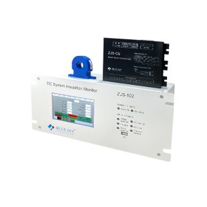
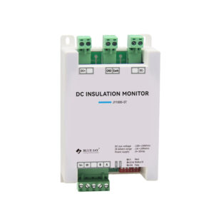
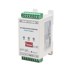
An unbalanced bridge DC insulation monitoring relay works by intentionally introducing an imbalance into a bridge circuit within the DC system. By measuring the resulting voltage or current variations, the system assesses the insulation integrity. Unlike the balanced bridge, which seeks a null point, the unbalanced bridge detects changes in the output signal that directly correlate to shifts in insulation resistance. This allows for the calculation of resistance values and the prompt triggering of alarms. This approach is particularly effective in tracking dynamic insulation resistance changes, enabling early detection of potential faults. If you want to find a DC insulation monitoring device with this working principle, we can offer you a ZJS102 DC insulation monitoring device and JY series Insulation monitoring device.
3. Signal injection working principle for IMD
Signal injection DC insulation monitoring operates by introducing a specific frequency signal into the DC system, acting as a diagnostic probe. The device then analyzes the signal’s path to the ground through the system’s insulation resistance. In a system with good insulation, the signal flow to the ground is minimal. Conversely, a decrease in insulation results in an increased signal flow. By measuring the magnitude of this signal, the monitoring device calculates the insulation resistance and triggers alarms as needed. This method is particularly effective for tracking insulation resistance variations, making it well-suited for complex DC installations. If you want to find an insulation monitoring device with a signal injection working principle, we can offer you a JY1000-EV DC insulation monitoring device.

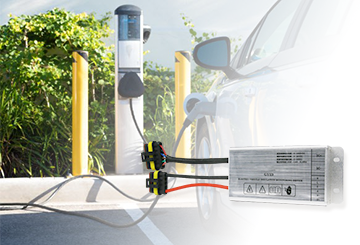
JY1000-ev DC Insulation Monitoring Device For EV Car
High safety for electrical vehicle insulation monitoring.
EV battery insulation monitoring. CE cerfitifaction Approved!
What are differences between them?
The three insulation monitoring device working principles can be categorized as either bridge methods or signal injection. Both balanced and unbalanced bridges fall under the bridge method category. What are the key differences between them?
Parameters Bridge Methods Signal Injection Sampling accuracy High Normal Sampling time When the insulation is normal, the sampling time is long. The lower the insulation value, the shorter the sampling time The first sampling time after power-on is longer Circuit structure Need high voltage No high voltage is required, AC pulse is required Detection position High voltage positive/vehicle ground
High voltage negative/vehicle ground High voltage bus/vehicle ground EMC performance High Normal Cost Can be reused with high voltage detection circuits such as pre-charge detection and relay diagnosis High voltage detection circuit cannot be reused Stability Better Better
Practical application examples of insulation monitoring device
The insulation monitoring of the DC power system involves the insulation monitoring of the DC bus as well as the insulation monitoring of each load branch. In practical applications, bus monitoring and branch monitoring will adopt different monitoring principles. The combination of them forms the insulation monitoring of the entire DC power system. The basic working principle of an insulation monitoring device is the following:
Under normal conditions, the busbar insulation monitoring is always active, and the busbar voltage deviation (the decrease in single-ended insulation resistance directly reflects the busbar-to-ground voltage offset) or the decrease in busbar-to-ground insulation resistance can initiate the detection of a branch circuit.
Branch monitoring typically operates in standby mode. Only when the insulation of the busbar is abnormal will the insulation examination of each branch be initiated in order to locate the appropriate insulation fault branch.
1. Application of DC busbar insulation monitoring device working principle

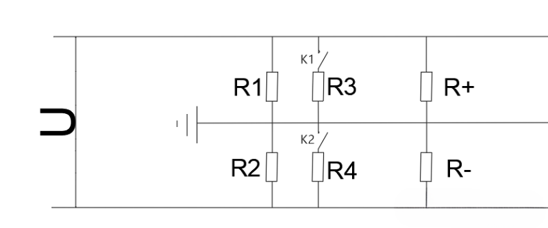
As illustrated in the figure above, R+ and R- are the equivalent insulation resistances of the positive and negative busbars to the ground, while R1 and R2 are the balance resistances of the positive and negative busbars to the ground, respectively. These two resistors help to balance the voltage of the busbar to the ground under typical conditions, preventing the voltage of the busbar from becoming unstable due to the busbar’s excessive insulation resistance to the ground. The two groups of resistances switched by K1 ~ K2 are different, so the measured positive and negative bus voltages are different, so as to calculate the insulation resistance to the ground.
First, Under normal circumstances:
The positive and negative bus-to-ground voltages U1 and U2 are measured to derive the equations for R+ and R-. All switches (K1, K2) are disconnected. That is, under normal circumstances, the insulation resistance of positive and negative busbars to the ground.
Second, when a positive or negative bus voltage offset happens, you need:
(1) first close the switch K1, K2, and then measure the positive and negative bus-to-ground voltage U1, U2 to obtain the formulae for R+ and R-.

(2) After disconnecting K1, measure the positive and negative busbar voltages at U1 and U2, then use the results to derive the formulae for R+ and R-.

The grounding resistance of the positive and negative busbars can be properly identified by measuring the grounding resistance of the positive and negative busbars using the unbalanced bridge method.
2. Application of DC branch circuit Insulation monitoring device working principle
To pinpoint insulation faults in DC power systems, leakage current is measured at branch outputs. This determines insulation resistance and triggers alarms. Two branch monitoring methods exist: AC and DC small signal detection.
AC small signal detection injects a low-frequency AC signal between the DC bus and ground. Branch current transformers then monitor ground leakage current to calculate insulation resistance. However, AC methods are complex. Cable capacitance and bus equipment can cause significant measurement errors, requiring complex compensation circuits or algorithms. Due to this complexity, AC small signal detection is rarely used today
Modern branch insulation detection typically employs DC leakage current sensors, leveraging the progress in semiconductor technologies like Hall effect sensors and general-purpose amplifiers.

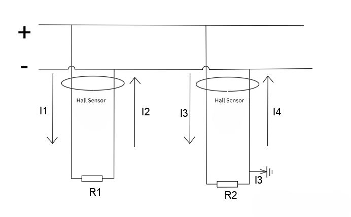
Leakage current detection is typically carried out on the branch output of the power system in order to precisely determine the fault point of the insulation drop of the DC power system. The corresponding magnitude of insulation resistance is then determined in accordance with the magnitude of the leakage current, and an alarm is given for the branch insulation fault.
The leakage current sensor is simultaneously passed through both the positive and negative connections. The positive and negative wires’ DC and DC currents are equal in size and flow in the opposite direction when there is no insulation drop, therefore the Hall sensor won’t produce an induction signal. The current flowing through the positive and negative poles will no longer be equal when one pole is grounded or when the insulation is decreased. The Hall sensor will now pick up the current difference signal.
Related Artilces
Tags
Company News
When it comes to the insulation monitoring device working principle, three primary monitoring principles are currently used: balanced bridge, unbalanced bridge, and signal injection. In this article, we’ll break down how DC insulation monitoring device works with practical applications.
Insulation Monitoring Device Working Princple Overview
1. Balanced Bridge working Principle for IMD
DC insulation monitoring device using a balanced bridge works like a precise seesaw. It uses a Wheatstone bridge to compare the insulation resistance between the DC system’s positive and negative poles to ground against known resistors. When insulation is good, the bridge is balanced, and the output voltage is near zero. If insulation fails, the resistance becomes unbalanced, the voltage changes and the insulation monitoring device triggers an alarm, safeguarding the DC system. If you want to find insulation monitoring device with this working principle, we can offer you ZJJ DC insulation monitoring device.
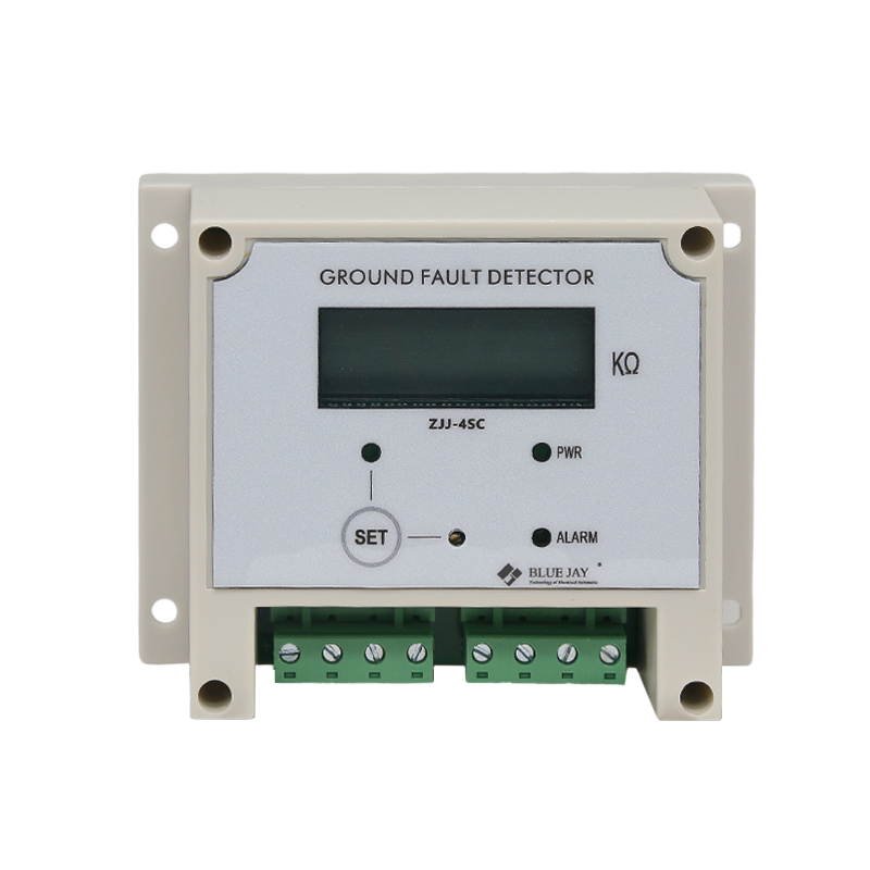
- Bridge balance method for resistance measurement.
- Smaller short-circuit grounding current for safe operation.
- Alarm resistance threshold online display and direct setting.
- Monitoring the DC circuit bus bar’s RF-to-earth insulation resistance.
2. unbalanced bridge working principle for IMD
An unbalanced bridge DC insulation monitoring relay works by intentionally introducing an imbalance into a bridge circuit within the DC system. By measuring the resulting voltage or current variations, the system assesses the insulation integrity. Unlike the balanced bridge, which seeks a null point, the unbalanced bridge detects changes in the output signal that directly correlate to shifts in insulation resistance. This allows for the calculation of resistance values and the prompt triggering of alarms. This approach is particularly effective in tracking dynamic insulation resistance changes, enabling early detection of potential faults. If you want to find a DC insulation monitoring device with this working principle, we can offer you a ZJS102 DC insulation monitoring device and JY series Insulation monitoring device.
3. Signal injection working principle for IMD
Signal injection DC insulation monitoring operates by introducing a specific frequency signal into the DC system, acting as a diagnostic probe. The device then analyzes the signal’s path to the ground through the system’s insulation resistance. In a system with good insulation, the signal flow to the ground is minimal. Conversely, a decrease in insulation results in an increased signal flow. By measuring the magnitude of this signal, the monitoring device calculates the insulation resistance and triggers alarms as needed. This method is particularly effective for tracking insulation resistance variations, making it well-suited for complex DC installations. If you want to find an insulation monitoring device with a signal injection working principle, we can offer you a JY1000-EV DC insulation monitoring device.
JY1000-ev DC Insulation Monitoring Device For EV Car
High safety for electrical vehicle insulation monitoring.
EV battery insulation monitoring. CE cerfitifaction Approved!
What are differences between them?
The three insulation monitoring device working principles can be categorized as either bridge methods or signal injection. Both balanced and unbalanced bridges fall under the bridge method category. What are the key differences between them?
| Parameters | Bridge Methods | Signal Injection |
| Sampling accuracy | High | Normal |
| Sampling time | When the insulation is normal, the sampling time is long. The lower the insulation value, the shorter the sampling time | The first sampling time after power-on is longer |
| Circuit structure | Need high voltage | No high voltage is required, AC pulse is required |
| Detection position | High voltage positive/vehicle ground High voltage negative/vehicle ground | High voltage bus/vehicle ground |
| EMC performance | High | Normal |
| Cost | Can be reused with high voltage detection circuits such as pre-charge detection and relay diagnosis | High voltage detection circuit cannot be reused |
| Stability | Better | Better |
Practical application examples of insulation monitoring device
The insulation monitoring of the DC power system involves the insulation monitoring of the DC bus as well as the insulation monitoring of each load branch. In practical applications, bus monitoring and branch monitoring will adopt different monitoring principles. The combination of them forms the insulation monitoring of the entire DC power system. The basic working principle of an insulation monitoring device is the following:
Under normal conditions, the busbar insulation monitoring is always active, and the busbar voltage deviation (the decrease in single-ended insulation resistance directly reflects the busbar-to-ground voltage offset) or the decrease in busbar-to-ground insulation resistance can initiate the detection of a branch circuit.
Branch monitoring typically operates in standby mode. Only when the insulation of the busbar is abnormal will the insulation examination of each branch be initiated in order to locate the appropriate insulation fault branch.
1. Application of DC busbar insulation monitoring device working principle

As illustrated in the figure above, R+ and R- are the equivalent insulation resistances of the positive and negative busbars to the ground, while R1 and R2 are the balance resistances of the positive and negative busbars to the ground, respectively. These two resistors help to balance the voltage of the busbar to the ground under typical conditions, preventing the voltage of the busbar from becoming unstable due to the busbar’s excessive insulation resistance to the ground. The two groups of resistances switched by K1 ~ K2 are different, so the measured positive and negative bus voltages are different, so as to calculate the insulation resistance to the ground.
First, Under normal circumstances:
The positive and negative bus-to-ground voltages U1 and U2 are measured to derive the equations for R+ and R-. All switches (K1, K2) are disconnected. That is, under normal circumstances, the insulation resistance of positive and negative busbars to the ground.
Second, when a positive or negative bus voltage offset happens, you need:
(1) first close the switch K1, K2, and then measure the positive and negative bus-to-ground voltage U1, U2 to obtain the formulae for R+ and R-.

(2) After disconnecting K1, measure the positive and negative busbar voltages at U1 and U2, then use the results to derive the formulae for R+ and R-.

The grounding resistance of the positive and negative busbars can be properly identified by measuring the grounding resistance of the positive and negative busbars using the unbalanced bridge method.
2. Application of DC branch circuit Insulation monitoring device working principle
To pinpoint insulation faults in DC power systems, leakage current is measured at branch outputs. This determines insulation resistance and triggers alarms. Two branch monitoring methods exist: AC and DC small signal detection.
AC small signal detection injects a low-frequency AC signal between the DC bus and ground. Branch current transformers then monitor ground leakage current to calculate insulation resistance. However, AC methods are complex. Cable capacitance and bus equipment can cause significant measurement errors, requiring complex compensation circuits or algorithms. Due to this complexity, AC small signal detection is rarely used today
Modern branch insulation detection typically employs DC leakage current sensors, leveraging the progress in semiconductor technologies like Hall effect sensors and general-purpose amplifiers.
Leakage current detection is typically carried out on the branch output of the power system in order to precisely determine the fault point of the insulation drop of the DC power system. The corresponding magnitude of insulation resistance is then determined in accordance with the magnitude of the leakage current, and an alarm is given for the branch insulation fault.
The leakage current sensor is simultaneously passed through both the positive and negative connections. The positive and negative wires’ DC and DC currents are equal in size and flow in the opposite direction when there is no insulation drop, therefore the Hall sensor won’t produce an induction signal. The current flowing through the positive and negative poles will no longer be equal when one pole is grounded or when the insulation is decreased. The Hall sensor will now pick up the current difference signal.

