15 Frequently Asked Questions of Digital Multifunction Power Meter
The digital multifunction power meter is a multi-functional smart

As for the multifunction meter connection diagram, this article will introduce it from the Blue Jay multifunction meter wiring diagram and key points, tips, and precautions for all MFM meter wiring.
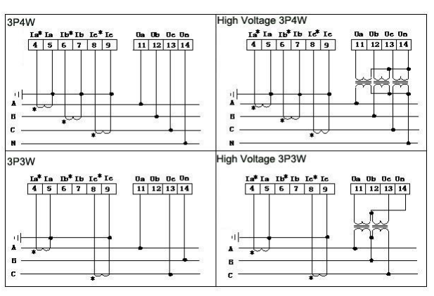
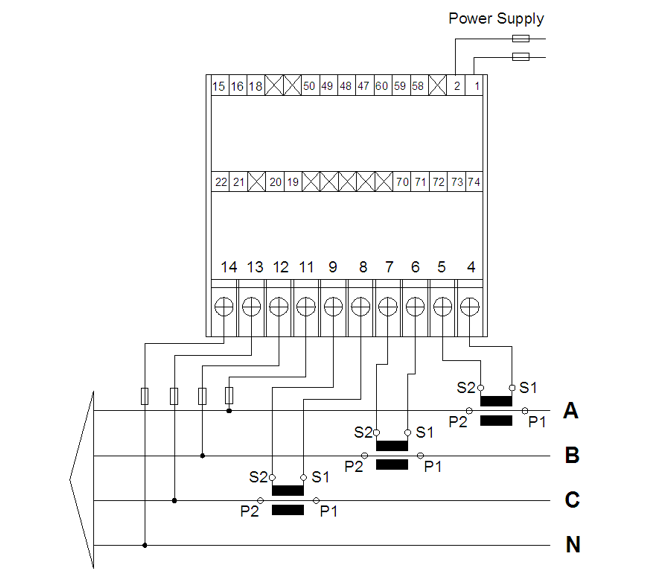
As for the MFM meter wiring diagram, you need to pay attention to the connection mode and interface of each part. Generally speaking, you need to read the manual first to understand the functions of each interface and the corresponding cable connection method, to avoid data errors caused by incorrect connections. Here is the Blue Jay multifunction meter connection diagram in the following:

This multifunction meter wiring diagram is suitable for 194J, 194Y, and 194Z multifunctional meters.

This multifunction meter wiring diagram is suitable for a 194Q multifunctional meter.

This multifunctional meter wiring diagram is suitable for 194DR.
Auxiliary power supply: The mfm energy meter has a universal (AC/DC) switching power supply input interface, and the limit working power supply voltage of the mfm meter is AC/DC: 80-270V. Please ensure that the provided power supply is suitable for this multi function digital meter to prevent damage to the product. If AC power is used, it is recommended to install a 1A fuse on the live wire side. For areas with poor power quality, it is recommended to install a surge suppressor in the power circuit to prevent lightning strikes and a fast burst suppressor.
Signal input: The multifunction meter with RS485 uses a computation approach that separately collects data from each measurement channel, ensuring that the results are always consistent and symmetrical. It is ideal for various load shapes and has a range of wiring techniques.
Illustrate of MFM meter wiring
Voltage input: The input voltage should not be higher than the rated input voltage of the product (100V or 400V), otherwise PT should be considered, and a 1A fuse must be installed at the voltage input terminal.
Current input: The standard rated input current is 5A, if it is greater than 5A, an external CT should be used. If the used CT(current transformer) is connected to other instruments, the wiring should be connected in series. Before removing the current input connection of the product, the primary circuit of the CT must be disconnected or the secondary circuit should be shorted. It is recommended to use a terminal block instead of connecting to the CT directly, so as to facilitate disassembly and assembly.
Check that the input voltage and current are corresponding, that the phase sequence is consistent, and that the direction is consistent; otherwise, there will be numerical and symbol mistakes.
The configuration of the instrument input network is determined by the number of CTs in the system. In the case of 2 CTs, choose the three-phase three-wire two-element method; in the case of three CTs, choose the three-phase four-wire three-element method. The input network NET set in the instrument wiring and instrument programming should be consistent with the connection mode of the load to be measured, otherwise, the voltage or power measured by the instrument will be incorrect. Among them, in the three-phase three-wire system, the voltage measurement and display is the line voltage; in the three-phase four-wire system, the voltage measurement and display is the phase voltage.
1. On the fixed power distribution cabinet, choose a suitable place to open a mounting hole with the same size as the opening.
2. Take out the multi-function power meter and remove the fixing clip.
3. Install the mfm meter into the meter hole of the power distribution cabinet.
4. Insert the fixing clip of the instrument.
The mfm meter measures all commonly used power parameters in three-phase power grid systems. Then, what problems should you pay attention to when installing and using them? Here are 11 points to note when using the mfm meter.
1. Before use, the mfm meter needs to be powered on for 15 minutes, suitable for use at an ambient temperature of 0-50°C and humidity below 85%, to prevent adverse phenomena caused by temperature changes.
2. Be careful of vibration and shock. It should be used in places with excessive dust and harmful gas.
3. Do not use the mfm meter in places where there is dust, or chemical experiments that are harmful to electrical products, gas, etc.
4. When the voltage is abnormal due to magnetic fields, high-frequency instruments, high-voltage sparks, lightning strikes, etc., please use external interference absorption circuits such as power line filters or nonlinear resistors.
5. The input signal line should be as short as possible. Use shielded wires where interference may occur. Generally speaking, if the input terminal of the signal to be tested is long, please try twisted-pair shielded wire.
6. If the mfm meter has no display, first check the auxiliary power supply to see if the voltage is within the range.
7. If the display is off, make sure the signal terminals are tightened and the input signal is normal.
8. The PT signal cannot be used simultaneously as an auxiliary power supply to guarantee the instrument operates normally unless the PT has sufficient power.
9. The current terminal screws in the CT circuit must be tightened to ensure reliable contact with the incoming/outgoing lines to avoid malfunctions.
10. If you want to calibrate the instrument, the calibration instrument should be better than 0.1 level to ensure calibration accuracy.
In addition, the multi-function meter is an instrument that converts the measured voltage value into digital form with an analog/digital converter and expresses it in digital form. Therefore, when the voltage is abnormal due to a magnetic field or high-frequency instrument, high-voltage spark, lightning, etc. Use a noise-absorbing circuit such as a power line filter or a non-linear resistor.
Related articles

15 Frequently Asked Questions of Digital Multifunction Power Meter
The digital multifunction power meter is a multi-functional smart

Multifunction Meter – Everything You Should Know
What is multifunction meter? This article will introduce it

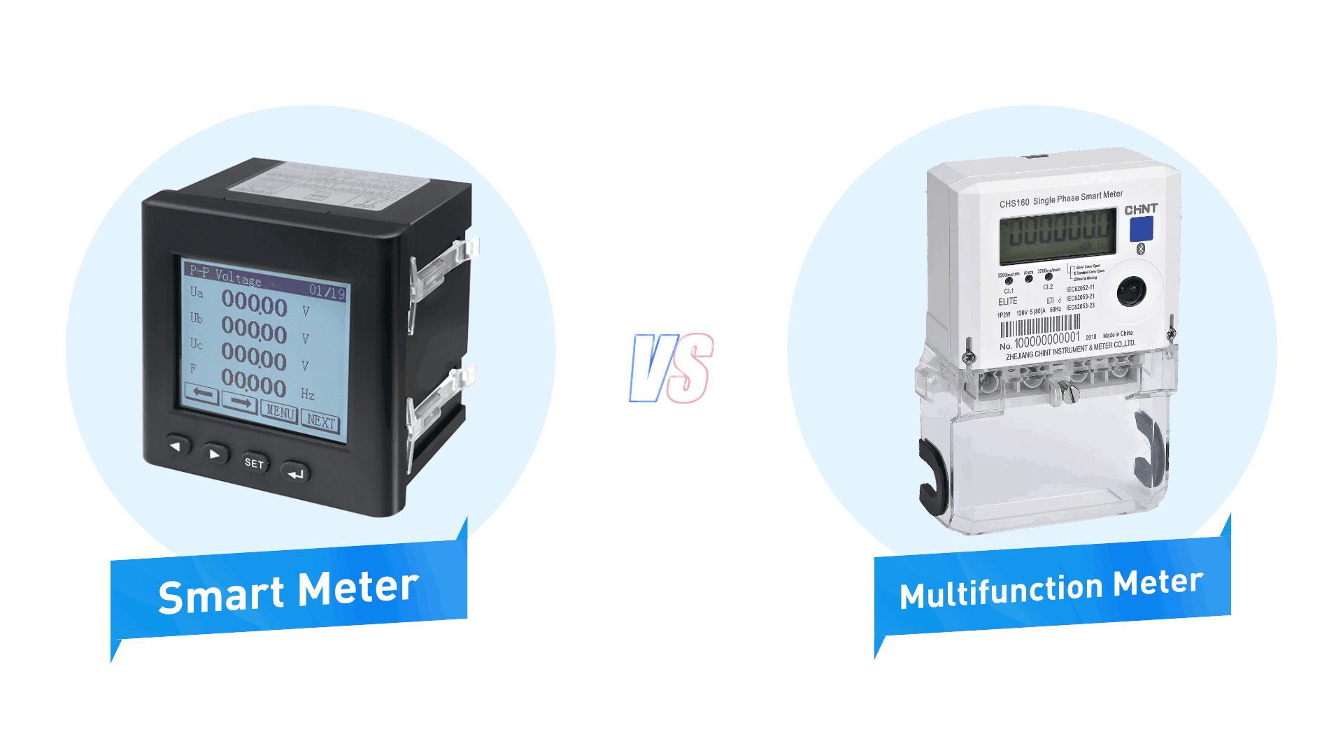
3 Differences Between the Multifunction Meter and Smart meter
Both the multifunction meter and the smart meter are


