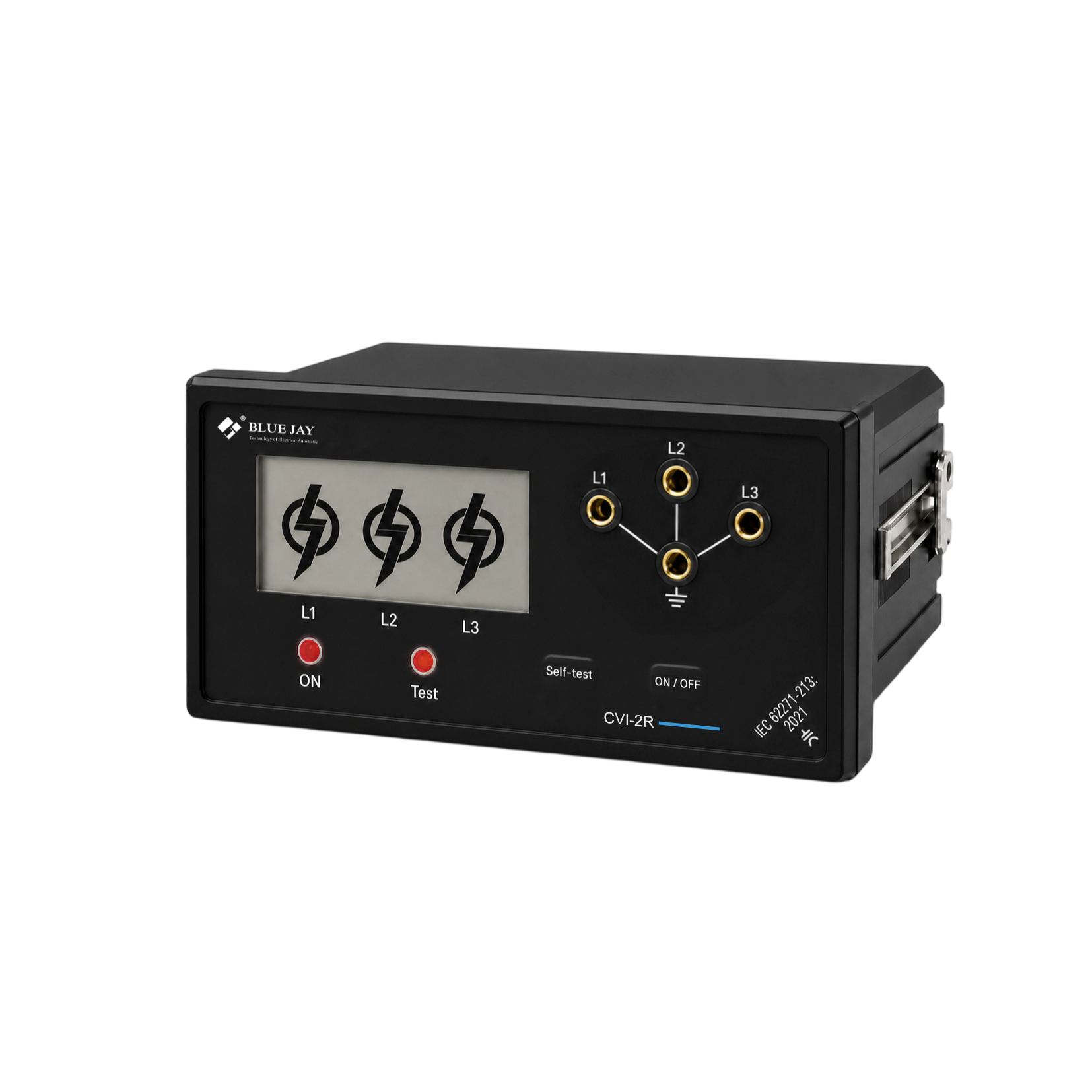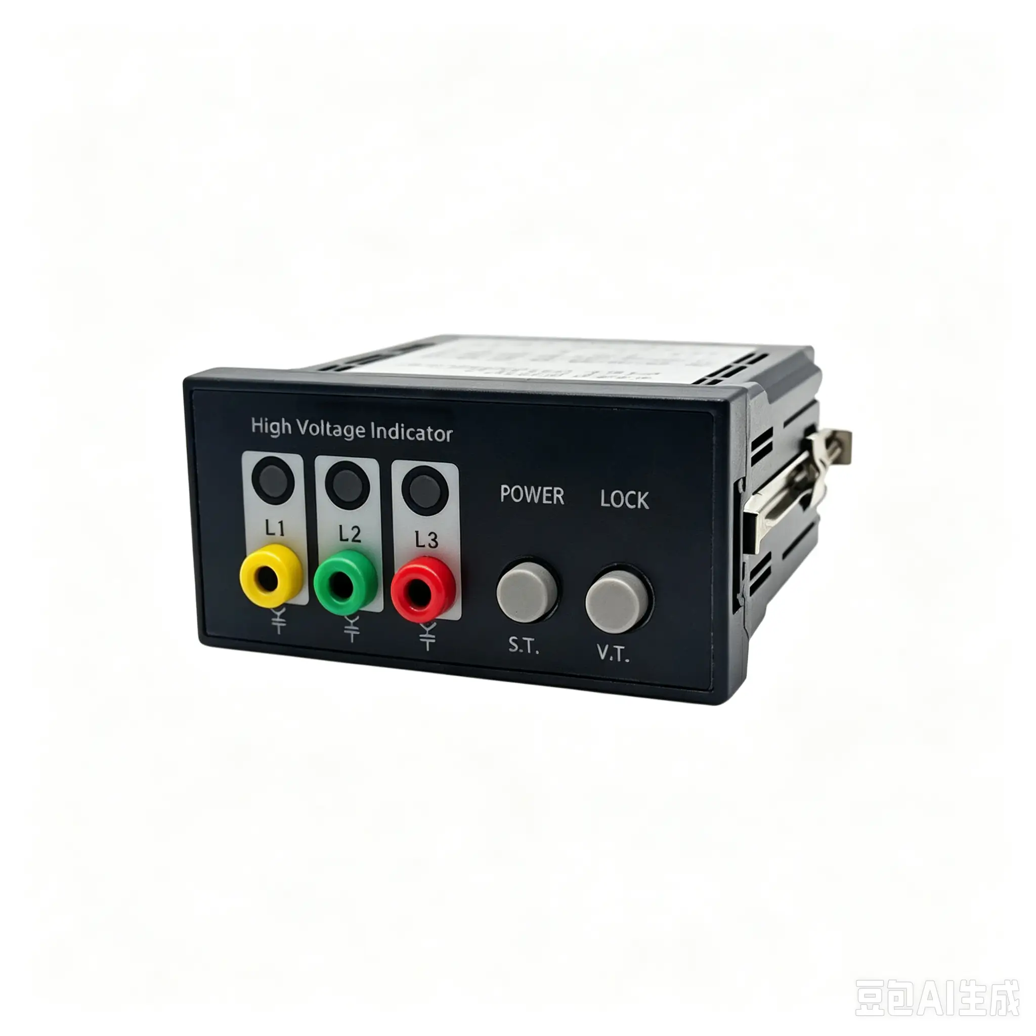
How to Choose the Right VDS for Your Coupling System
In medium-to-high voltage power distribution scenarios, Capacitive Voltage Detecting Systems (VDS) cannot be selected arbitrarily; their detection accuracy and operational safety depend critically on a precise match with the specific coupling system installed on-site. According to relevant IEC standards, coupling systems are categorized into five main types: LR, MR, LRM, LRP, and HR. Consequently, the corresponding VDS units must be selected to match the specific type and specifications of the coupling system to prevent detection errors and safety risks caused by mismatches in interfaces or electrical parameters.
Why Is the Coupling System Type Crucial for VDS Selection?
The ability of a VDS to accurately determine the live/energized status of a switchgear cabinet depends fundamentally on the voltage, current, and impedance signals output by the internal coupling components, as well as the device’s ability to correctly interpret these signals. Since the signal parameters vary significantly across different coupling systems, a mismatch between the VDS and the coupling system can easily lead to critical errors—such as falsely indicating that a circuit is live when it is not, or failing to detect a loss of power. Therefore, it is imperative to select a VDS unit with specifications that precisely match the actual coupling system installed at the site.
5 Types of Coupling Systems: Which One Does Your Switchgear Use?
| Coupling System Types | Typical User Scenarios | Key Electrical Parameters (Determining whether VDS is recognized) | Physical Interface Characteristics | Choosing a VDS |
| HR (High Impedance Type) | Medium-to-High Voltage Switchgear (Mainstream) | 70-90V / 36-43.2MΩ | 19mm Bipolar Connector | High-voltage scenarios are the most common; since the interface is subjected to high voltages, it is imperative to select a VDS with a corresponding voltage rating and input impedance. Failure to do so will prevent the “power present” detection from triggering. |
| MR (Medium Impedance Type) | Medium Voltage Switchgear | 20-30V / 12-14.4MΩ | 21mm Bipolar Connector | Designed specifically for medium-voltage scenarios, featuring moderate signal strength; requires matching of the input impedance and detection threshold with VDS to prevent false negatives. |
| LR (Low Impedance Type) | Legacy Switchgear (Installed Base) | 4-5V / 2-2.4MΩ | 6.3mm Phone Plug Connector | As a legacy issue from an older project, the interface dimensions are non-standard; consequently, many newer VDS models currently on the market do not support them. Therefore, compatibility must be verified in advance during the retrofit process. |
| LRM (Modified Low Impedance Type) | Modern Medium-to-Low Voltage Switchgear | 4-5V / 2-2.4MΩ | 14mm Bipolar Connector | The current mainstream low-impedance solution offers strong compatibility; however, it lacks reverse-polarity protection. Connecting it incorrectly will directly result in a false reading, thereby imposing strict requirements on operational protocol. |
| LRP (Cable Test Head Type) | Cable Compartment / Cable Test Point | 4-5V / 5-6MΩ | No Fixed Plug | Designed specifically for the cable side, this unit employs a specialized signal acquisition method; standard VDS units used in ordinary switchgear are incompatible. It is therefore mandatory to select a model specifically dedicated to cable testing. |
What are the application for coupling systems and Capacitive Voltage Detection Systems (VDS)?
For medium-to-high voltage equipment rated at 10kV and above—specifically in scenarios requiring non-contact voltage verification, live-line monitoring, electrical interlocking, or verification of de-energized status for maintenance—it is essential to pair the equipment with a compatible coupling system and Capacitive Voltage Detection System (VDS). Among these applications, nuclear power plants and large-scale power stations impose the most stringent requirements regarding equipment specifications and parameter matching.
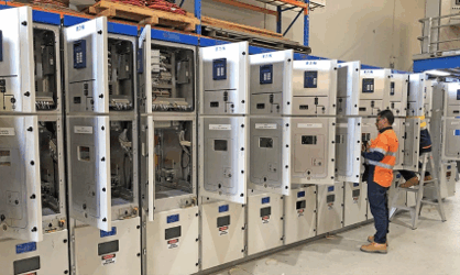
Medium-to-High Voltage Switchgear: Various indoor and outdoor high-voltage cabinets, ring main units, and gas-insulated switchgear—rated at 10kV, 24kV, or 35kV—are pre-installed with coupling components. When paired with a VDS, these systems enable non-contact determination of the live-line status and are widely utilized in power distribution rooms and substations.
Rail Transit Power Supply Systems: High-voltage equipment within the traction power supply systems of subways and high-speed railways operates under complex conditions and undergoes frequent maintenance. By relying on coupling-based sampling in conjunction with a VDS, these systems can stably monitor line voltage conditions.
Cable Distribution Facilities: Cable branch boxes and line test points are fitted with specialized LRP coupling systems and corresponding VDS units. This configuration enables precise detection of line energization status and residual voltage, thereby facilitating the identification and troubleshooting of potential line faults.
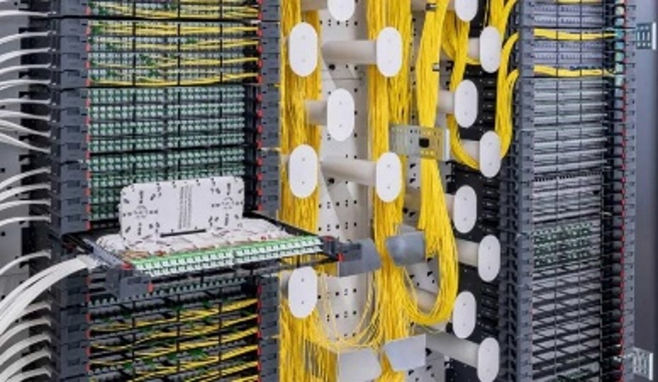
Nuclear Island and Conventional Island High-Voltage Distribution Cabinets: In the core power distribution zones of nuclear power plants—characterized by complex electromagnetic environments and high safety standards—interference-resistant coupling components and specialized, nuclear-grade VDS units are employed to reliably determine the operational status of high-voltage circuits.
Nuclear Power Grid-Connection Switchgear: High-voltage cabinets dedicated to grid-connection and power transmission strictly adhere to the IEC 61243-5 standard regarding the configuration of coupling structures, utilizing a VDS to verify the electrical status prior to grid synchronization.
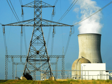
Nuclear Power Outdoor Distribution Equipment: Outdoor high-voltage facilities within the plant premises are equipped with radiation-resistant, wide-temperature-range coupling accessories and specialized VDS units, specifically designed to withstand the harsh outdoor operating environments typical of nuclear power stations.
How to Select the Appropriate VDS for a Coupled System
The key to selecting a suitable VDS (Capacitive Voltage Detection System) lies in ensuring it is perfectly matched with the specific coupling system installed on-site.
- Identify the Type of Coupling System: Consult the switchgear’s factory documentation, interface specifications, or the nameplate on the coupling components to determine the specific type of built-in coupling structure (e.g., LR, MR, LRM, LRP, or HR). Strictly select a VDS that corresponds precisely to this coupling system type to ensure compatibility of both the physical interface and electrical parameters, thereby preventing detection errors. For instance, for an HR-type coupling system, select a VDS specifically designed for HR systems.
- Determine the Equipment Voltage Class: Based on the on-site distribution voltage levels—such as 10 kV, 24 kV, or 35 kV—verify that the VDS’s rated withstand voltage meets the requirements of the local power supply system.
- Select Based on Application Scenario: For standard substations and distribution rooms, opt for conventional, general-purpose models. For cable testing points, prioritize the use of specialized LRP-compatible VDS units. For complex operating environments—such as rail transit systems—select models featuring enhanced anti-interference capabilities.
- Verify Compliance: Ensure that the selected VDS complies with relevant IEC standards and is capable of accurately interpreting the signals generated by the coupling system, thereby preventing false indications.
Conclusion
In conclusion, the interface specifications, resistance values, and voltage determination criteria of a coupling system directly dictate the selection specifications for the Voltage Detection System (VDS). Different models must be strictly and precisely matched; arbitrary combinations will result in detection failures and erroneous judgments, while also posing significant safety hazards. Only by accurately identifying the type of coupling system and selecting the appropriate equipment in strict accordance with established standards can the voltage detection device effectively fulfill its safety monitoring function.