
5A vs 1A Secondary Current Transformer
What is a secondary current transformer?
Secondary current transformers are specifically designed for use with power instruments, electricity meters, and protection devices. Since high-voltage or high-current circuits cannot be measured directly by instruments, the transformer converts the large primary alternating current into a standardized, smaller current (with industry-standard rated secondary currents of 1A or 5A) based on a fixed transformation ratio; this output is known as the secondary current, and the transformer performing this conversion function is referred to as a secondary current transformer.
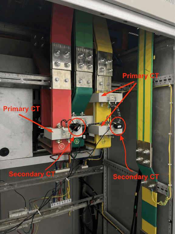
1A vs. 5A CT – What is the difference?
Standard power distribution projects typically utilize current transformers with a secondary rated current of 5A, whereas 1A secondary transformers are better suited for long-distance metering applications. Since the transformer’s secondary circuit relies on cables to transmit the sampled current, excessive wiring distances significantly increase total line resistance.
This leads to additional power loss and voltage drop, directly causing inaccuracies in ammeter and electricity meter readings. Consequently, the 1A secondary transformer is the superior choice for scenarios involving large distances between the transformer and the measurement terminal. Let us now examine the specific differences between 1A and 5A transformers.
Differences in Line Power Loss
Line power loss is proportional to the square of the circuit current. Given identical wire cross-sectional areas and transmission distances, the line power loss of a 1A secondary transformer is merely 1/25 (or 4%) of that of a 5A transformer.
Referring to the data in the “Power Loss in Current Transformer Measurement Circuits” sheet: for a 1.5mm² cable with a transmission distance of 10m, the line power loss for a 5A circuit is 5.86 VA, whereas for a 1A circuit, it is only 0.235 VA—clearly illustrating the vast difference.
Higher line power loss consumes the current transformer’s rated capacity and limits the maximum transmission distance. Therefore, in projects requiring long wiring runs, prioritizing 1A secondary current transformers effectively reduces cable losses and ensures metering and measurement accuracy. In summary, 1A secondary current transformers result in lower line power loss.
Power Loss in Current Transformer Measurement Circuits
| Wire Cross-Sectional Area (mm²) | CT Secondary Current (A) | 1m Transmission power consumption(VA) | 2m Transmission power consumption(VA) | 5m Transmission power consumption(VA) | 8m Transmission power consumption(VA) | 10m VA) |
| 1.5 | 1 | 0.023 | 0.047 | 0.117 | 0.188 | 0.235 |
| 1.5 | 5 | 0.59 | 1.17 | 2.93 | 4.68 | 5.86 |
| 2.5 | 1 | 0.014 | 0.028 | 0.07 | 0.112 | 0.14 |
| 2.5 | 5 | 0.35 | 0.7 | 1.76 | 2.82 | 3.52 |
| 4 | 1 | 0.009 | 0.018 | 0.045 | 0.072 | 0.098 |
| 4 | 5 | 0.22 | 0.44 | 1.1 | 1.76 | 2.2 |
Extended Transmission Distance
Cable power loss follows the formula P = I² × R, meaning the loss is proportional to the square of the current. Given identical cable specifications and transformer rated capacities, the power loss in a 5A secondary circuit is 25 times that of a 1A circuit; conversely, the power loss of a 1A circuit is only 4% of that of a 5A circuit.
Line losses consume the rated capacity of the current transformer; the higher the loss, the shorter the permissible wiring distance. Theoretically, under identical operating conditions, the effective transmission distance of a 1A CT can be up to 25 times that of a 5A CT.
Example: With a rated capacity of 2.5VA and 1.5mm² cabling, the maximum transmission distance is 106.5m for a 1A CT, compared to only 4.3m for a 5A CT.
Therefore, selecting a 1A current transformer for long-distance measurement scenarios eliminates the need for intermediate 5A/1A conversion transformers or high-capacity transformers. This approach reduces cable losses and ensures measurement accuracy while saving on equipment and wiring costs.
1A & 5A Secondary CT Transmission Distances
| Rated Capacity (VA) | Secondary Current (A) | Max Transmission Distance (m) – 1mm² Wire | Max Transmission Distance (m) – 1.5mm² Wire | Max Transmission Distance (m) – 2.5mm² Wire | Max Transmission Distance (m) – 4mm² Wire |
| 2.5 | 1 | 71 | 106.5 | 178 | 284 |
| 2.5 | 5 | 2.8 | 4.3 | 7.1 | 11.4 |
| 5 | 1 | 142 | 213 | 355 | 586 |
| 5 | 5 | 5.7 | 8.5 | 14.2 | 22.7 |
| 10 | 1 | 284 | 426 | 710 | 1186 |
| 10 | 5 | 11.4 | 17 | 28.4 | 45.5 |
Small Wire Cross-Sectional Area
In large and medium-sized factories, when the distance between the instrument and the current transformer is relatively short (e.g., 45.5 m), Table 2 shows that using a 5 A, 10 VA current transformer requires a calculated wire cross-sectional area of 4 mm²; conversely, at a distance of 71 m, selecting a 1 A, 2.5 VA current transformer requires a cross-sectional area of only 1 mm². With the widespread adoption and advancement of computers and digital instruments, the selection of current transformers with a rated secondary current of 1 A or less has become increasingly common.
Which application to Use a 1A CT/5A CT
Current transformers primarily provide standard sampling signals for AC/DC current measurement, energy metering, relay control, and fault protection systems. According to IEC and GB standards, secondary rated current is divided into two main specifications: 5A and 1A. Based on loop distance and downstream equipment type, the applicable scenarios are as follows:
5A Secondary Current Transformer Applications
5A is the traditional preferred specification in the industry, with strong versatility and wide compatibility with existing traditional electrical equipment. It is suitable for short-distance wiring conditions between the CT and downstream instruments.
- Local installation within switchgear cabinets, where the cable laying distance from the CT to the electric meter or protection relay is short (generally <10m);
- Traditional electromagnetic relay protection devices, pointer-type ammeters, and conventional electronic metering meters;
- Renovation projects in old substations and distribution rooms, where the existing equipment on site all have a 5A current input, ensuring compatible replacement;
- Low-voltage switchgear, local motor control cabinets, and workshop local monitoring circuits.
1A Secondary Current Transformer Applications
Leveraging its advantages of low power consumption and long-distance transmission, it is primarily designed for digital systems, remote centralized monitoring, and projects with long secondary cables.
- Digital substation protection and automation control systems based on the IEC 61850 standard, and modern microprocessor-based digital protection relays;
- Remote energy or electrical metering application: where the transformer installation location is far from the central control room and metering terminal (>10m);
- Large and medium-sized substations, photovoltaic/energy storage power stations, and factory centralized energy consumption monitoring systems;
- Projects with multiple instruments sampling in parallel on the secondary circuit and long total lengths of secondary cables.
Conclusion
In conclusion, 5A CT works best for short cable distances and legacy equipment upgrades. Thanks to far lower circuit power loss, 1A CT supports long-distance signal transmission and matches modern digital protection and remote monitoring systems. Proper selection of secondary current rating ensures reliable and accurate current sampling in your power system.
.png)