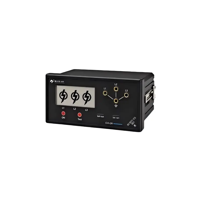
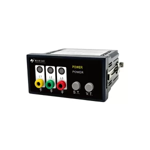
The CVI-2R voltage detecting and indicating system is designed for continuous indication of voltage on medium-voltage switchgear busbars. It provides continuous voltage presence indication and voltage absence verification in accordance with IEC 62271-213:2021. The device supports dual-stage voltage indication and overvoltage indication to improve operational safety during switching and maintenance procedures.
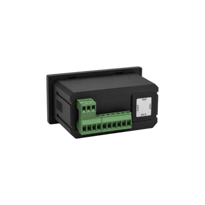
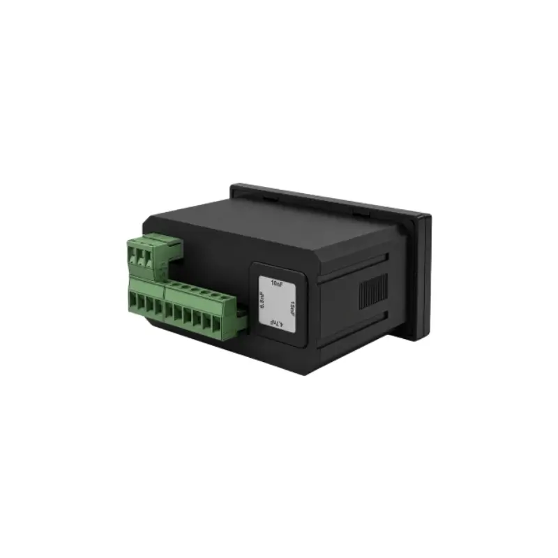
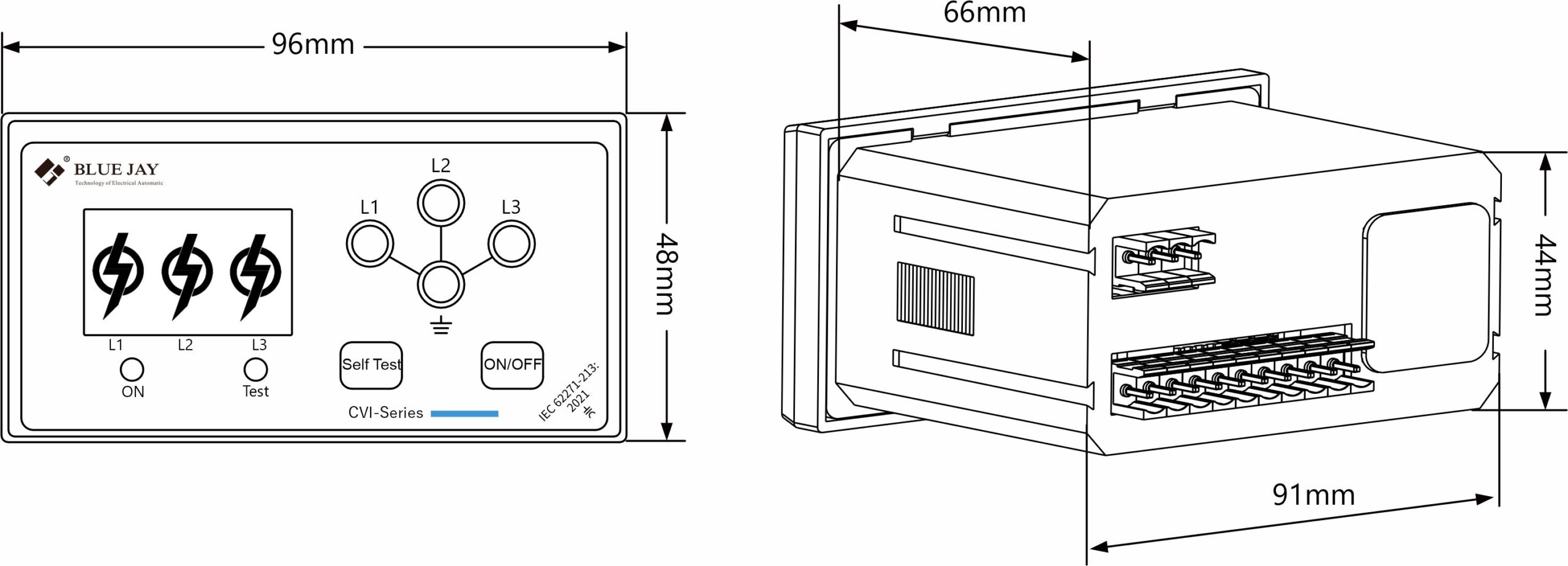
The front panel features two LED indicators and two dedicated pushbuttons for self-test and voltage presence verification. An integrated three-phase LRM measuring point supports phase comparison and phase sequence verification for safe commissioning and maintenance. An adjustable capacitance module is provided to optimize the capacitive voltage division ratio. Two relay outputs are available for alarm, interlock, and remote indication applications. With a compact 96× 48mm design and a wide auxiliary power supply range of 85–265 Vac/dc, the CVI-2R is suitable for various switchgear installations.
Two channels relay outputs for remote status monitoring;
Self-test function ensures reliable operational verification;
Integrated phase sequence detection;
Application
Medium-voltage power distribution;
Transmission and distribution systems;
Power generation facilities applications;
Industrial power distribution systems;
Data center power infrastructure;
Specification
Parameter
Value
Power supply
85-265Vac/dc
Rated voltage
1kV -35kV
Power consumption
Less than 2W
Voltage threshold
10% to 45%Un
Capacitance Module
200pF/ 125pF /80pF/ 45pF
Rated frequency
50-60Hz
Relay output
2 channel, passive, dry contact, normally open
Load capacity: 10A @250Vac/5A@ 30Vdc
LED indicator
Ultra-high brightness LED
operating voltage < 2.5Vdc, service life > 50,000 hours.
Insulation
Input, output, power supply to shell >5MΩ
Withstand voltage
2 kV AC RMS 1 minute, between power supply to ground/ between relay contact to ground.
Standards
Compliant with IEC 62271-213
Installation dimension
WxHxD: 96x48x66mm
Working environment
-25~70°C, Altitude ≤2000m,
0~95%RH, non-condensing, non-corrosive gas
Adaptation capacity parameter table:
Voltage Level (kV)
6
10
24
35
Adaptable Capacitance (pF)
200(±15)
125(±15)
80PF(±10)
45(±10)
Dimension (Height * Width)
140x95mm
210x110mm
320x145mm
Working principle
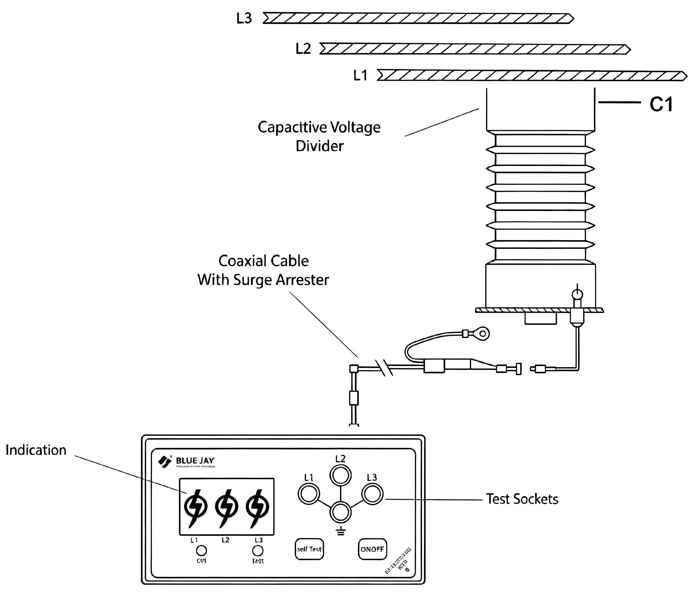
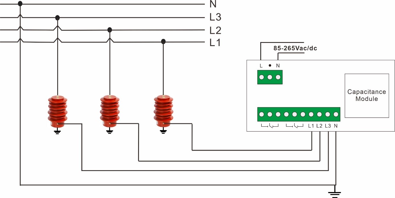
The CVI-2R capacitive voltage indicator operates on the principle of capacitive coupling. An electrode connected to each medium-voltage phase conductor forms a coupling capacitance with the primary conductor and, together with the circuit capacitance to earth, establishes a capacitive voltage divider. This converts the primary voltage into a low-level sensing signal without a direct conductive connection to the high-voltage conductor.
The CVI-2R processes the three-phase sensing signals and indicates voltage status according to preset thresholds, including dual-stage voltage indication and overvoltage indication. Dedicated self-test and voltage verification buttons support functional checks and voltage absence verification, while the three-phase LRM test interface enables phase comparison and phase sequence verification. Relay outputs provide additional interfaces for remote indication and interlocking.
Chongqing Blue Jay Technology Co., Ltd. was founded by engineers with 10+ years of experience. Focuses on the development, production and sales of power automation monitoring products and energy metering instruments.