Insulation Monitoring Coupling Device – A complete Guide
What is a coupling device for insulation monitoring devices?
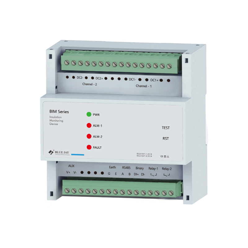
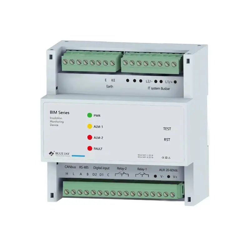
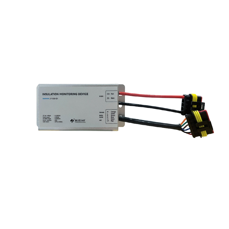
An insulation monitoring coupling device is a dedicated extension device for insulation monitoring instruments and an important component of power insulation monitoring systems. Its core function is to overcome the limitations of conventional insulation monitoring instruments in terms of voltage range and scenario adaptability, effectively expanding the operating voltage range and system compatibility of insulation monitoring equipment. This allows ordinary insulation monitoring instruments to be adapted to high-voltage, multi-phase, and AC/DC hybrid IT ungrounded power systems, solving the pain points of insufficient range and inability to monitor complex power grids by conventional monitoring equipment. It comprehensively ensures the safe operation of power system insulation under various operating conditions and is widely applicable to various industrial and high-reliability power supply scenarios.
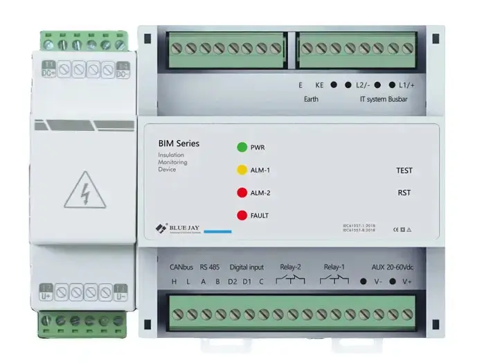
In short, the coupling device expands the adaptability of the input circuit of the insulation monitoring device, enabling monitoring of multi-phase IT power networks and power grids with higher operating voltage levels. Taking common models as an example, the insulation monitoring instrument itself is compatible with up to 800V AC/DC ungrounded systems; for single-phase AC, three-phase AC, and DC ungrounded systems with voltages higher than 800V, by pairing it with a corresponding coupler, insulation monitoring of high-voltage systems can be completed.
What are the types of insulation monitoring coupling devices?
Based on the applicable grid voltage level and power supply architecture, insulation monitoring coupling devices can be divided into two categories, comprehensively covering the monitoring needs of high and low voltage AC/DC ungrounded systems.
The first type is a general-purpose coupling device, suitable for conventional ungrounded power systems with single-phase AC 0–1150V and DC 0–1760V, applicable to most common industrial power distribution scenarios.
The second type is a composite coupling device, suitable for more complex high-voltage systems, supporting three-phase AC 0–1650V ungrounded systems, as well as AC/DC composite ungrounded systems with DC components such as rectifiers and a voltage range of 0–1300V. It is specifically designed for complex operating conditions such as industrial high-voltage power supply and AC/DC mixed power supply, and the corresponding model can be matched according to the on-site system parameters.
How does an insulation monitoring coupler work?
The insulation monitoring coupler employs a non-contact signal coupling principle, working in tandem with an insulation monitor to perform comprehensive insulation monitoring. Without requiring the monitoring host unit to connect directly to the primary high-voltage grid, the device uses a specialized coupling structure to inject a precisely optimized, low-level standardized test signal between the power system’s phase lines and the ground. This enables continuous data acquisition and dynamic monitoring of the grid’s insulation status. This method accurately captures subtle fluctuations in system insulation resistance, allowing for the early detection of fault trends—such as insulation aging or latent grounding issues—and the issuance of timely alarms, thereby preventing equipment anomalies and power outages caused by insulation failures at the source. Furthermore, the low-level test signal does not interfere with the normal operation of power equipment, permitting precise monitoring without system downtime and ensuring a balance between monitoring accuracy and grid operational stability.
IEC 61557 - 8 & IEC 61326 - 2 – 4 for insulation monitoring coupling device
Coupling devices for insulation monitoring must comply with the international standards IEC 61557-8 and IEC 61326-2-4. Compliance with IEC 61557-8 ensures accurate insulation monitoring and reliable alarming, meeting the specifications for unearthed IT systems; adherence to the IEC 61326-2-4 electromagnetic compatibility standard guarantees robust interference resistance in complex industrial environments, minimizes false alarms, and facilitates smooth project acceptance both domestically and internationally.
Application of Insulation Monitoring Coupling Devices
Insulation monitoring coupling devices are primarily used in sectors requiring high levels of power supply continuity and safety—such as electric power, industry, commerce, new energy, healthcare, data centers, rail transit, and marine shipping—and are particularly suited for IT power systems with ungrounded or high-impedance grounded neutral points. Through their coupling and expansion capabilities, these devices accommodate various voltage levels, mixed AC/DC systems, and complex distributed grid architectures. They enable comprehensive, high-precision monitoring of insulation status, effectively mitigating risks of equipment damage and downtime caused by insulation aging, latent leakage, and ground faults.
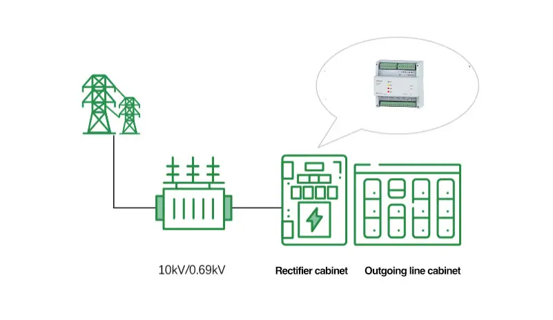
In power systems: these devices are widely deployed on core primary equipment—such as high-voltage switchgear and transformers in substations—to continuously monitor grid insulation status and ensure the stable operation of high-voltage distribution systems, serving as a vital component for safety management in power operations and maintenance.
In industrial sectors: including continuous production industries like chemicals, metallurgy, and steel manufacturing—the devices provide real-time insulation monitoring for production line motors, cables, and control circuits. Their coupling functionality allows coverage across multiple branch subsystems, effectively preventing major production losses such as equipment burnout or line shutdowns caused by insulation faults.
In commercial and civil buildings: the devices integrate with public power distribution networks in office buildings and shopping centers, accurately identifying electrical hazards caused by factors like humidity or aging wiring. Their highly compatible coupling structure allows for direct integration into existing power monitoring systems without requiring extensive modifications, making them ideal for upgrading older facilities.
In the new energy sector: the devices address the complex DC grid structures found in distributed energy systems like photovoltaics and wind power. Leveraging their coupling and adaptability, they enable precise DC-side insulation monitoring, ensuring the safe and stable operation of new energy generation systems.
In high-reliability power supply scenario: the devices help hospital power systems mitigate leakage risks and ensure the uninterrupted, stable operation of precision medical equipment. For data centers, they safeguard insulation integrity throughout the power supply chain, preventing major losses—such as equipment downtime or data loss—caused by electrical faults. Additionally, the devices are suitable for electrical systems in specialized operating environments, such as marine vessels and railway traction power supplies, meeting the need for highly reliable insulation monitoring under demanding conditions.
Regarding implementation, the equipment meets the distinct requirements of both new construction projects and retrofit projects for existing facilities. For retrofit projects involving switchgear with limited space, a rail-mounted coupling device paired with a split-core zero-sequence current transformer can be used; this allows for rapid installation without disconnecting cables, significantly reducing downtime during construction. For new projects, an integrated calibration-ready coupling device paired with a high-precision zero-sequence current transformer can be selected to accurately detect potential issues such as low-resistance faults and progressive insulation degradation, thereby comprehensively enhancing the system’s insulation monitoring accuracy and early warning capabilities.
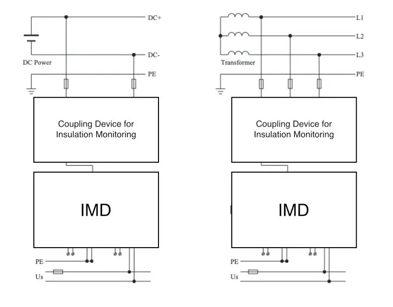
Insulation monitoring Couple Device Wiring diagram
The insulation monitoring coupling device is connected to the two lines of the monitored single-phase AC IT system, the positive and negative poles of the DC system, or the three phase lines of the three-phase AC IT system; simultaneously, the terminals of the coupling device are connected to the corresponding terminals of the insulation monitor.
FAQs of Insulation Monitoring Coupling Devices
Q: Does the installation orientation of the coupler affect monitoring results?
A: Yes. Couplers feature polarity markings (typically P1/P2 terminals); incorrect reverse connection causes phase inversion, leading to vector errors during the fusion calculation with zero-sequence signals. This can result in reduced sensitivity or, in cases of three-phase imbalance, trigger false alarms.
Q: How often should the insulation monitoring coupler be calibrated?
A: Professional calibration is generally recommended every 6 to 12 months; however, the calibration interval should be shortened for high-precision applications or if the equipment exhibits abnormalities.
Q: Why must the coupler and the zero-sequence current transformer (CT) be used together?
A: Deploying either the coupler or the zero-sequence CT in isolation is insufficient for an effective assessment of insulation status. The coupler—acting as the system’s “stethoscope”—non-contactly extracts power-frequency and high-frequency transient signals from high-voltage busbars or feeder cables. Meanwhile, the zero-sequence CT—installed around the three-phase cables (including PE/N lines)—is dedicated to detecting unbalanced leakage current, functioning like a “leakage detector.” Only by fusing and analyzing signals from both components can the system distinguish between normal capacitive current and actual insulation defects. Relying solely on a coupler makes the system prone to false alarms caused by electromagnetic interference, whereas using only a zero-sequence CT results in insufficient sensitivity regarding high-impedance grounding faults or distributed insulation degradation. Currently, acceptance standards for new distribution substations in many regions explicitly require dual-channel signal acquisition as a standard configuration for insulation monitoring.