
Open Delta PT Connection – A Comprehensive Guide
The open delta connection of voltage transformers (PTs) is a specialized secondary wiring configuration primarily used to measure system zero-sequence voltage and monitor for single-phase ground faults on the busbar. It serves as the core detection mechanism for insulation monitoring and ground fault alarming in 10kV distribution networks. This connection method is widely used in two mainstream types of distribution networks: systems with ungrounded neutral points and systems with neutral points grounded via arc-suppression coils. It is important to note that while this method can detect whether a ground fault has occurred on the busbar, it cannot directly pinpoint the specific faulty feeder circuit.
Working Principle of Open Delta PT Connection
Voltage transformers used for this purpose are typically either three-phase, five-limb units or a combination of three single-phase PTs. They feature two sets of secondary windings:
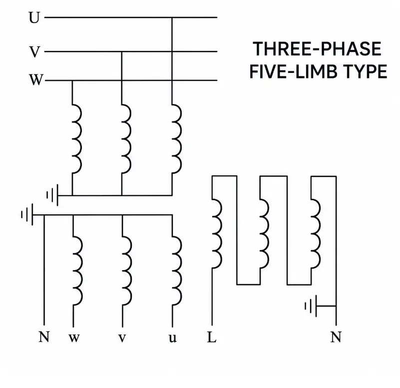
Main windings: Connected in a wye (star) configuration, these are used to measure phase and line voltages and serve as the core of standard voltage monitoring.
Residual windings: Connected in an open delta configuration. The three-phase windings are connected in series (end-to-start), with connections brought out only from the start terminal of the first winding and the end terminal of the last winding to form an open structure used for detecting zero-sequence voltage. The rated voltage for each phase of the residual winding is typically designed as 100/√3 V.
During normal operation, the three-phase voltages are symmetrical; the induced voltages in the open delta circuit are equal in magnitude and phase-shifted by 120°, resulting in a phasor sum of zero and an output voltage of 3U₀ ≈ 0 V (with only a negligible residual unbalance voltage present).
Upon the occurrence of a single-phase ground fault, zero-sequence voltage appears in the system, causing voltage asymmetry. The phasor sum of the three-phase voltages in the open delta circuit becomes non-zero, resulting in an output of three times the zero-sequence voltage.
The residual winding of the PT is designed with a rated phase voltage of 100/√3 V, and the transformation ratio is determined by the ratio of the primary phase voltage to this value. In the event of a solid (metallic) single-phase ground fault, the system’s zero-sequence voltage equals the rated phase voltage; the voltages from the three residual windings sum up to produce an output of exactly 100 V at the open delta terminals, allowing protection equipment to detect this voltage and trigger a ground fault alarm.
Open-delta PT connection in a non-solidly grounded system (isolated neutral system)
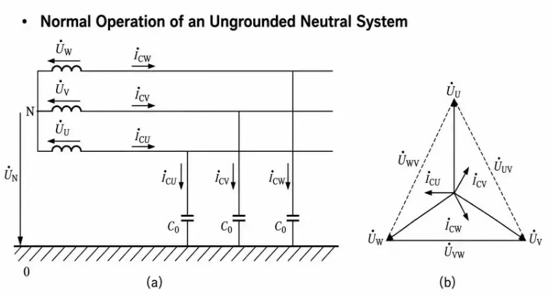
Primary-side voltage changes: Taking a 10kV non-solidly grounded system as an example, assume a solid (metallic) ground fault occurs on phase C. The voltage to ground of the faulted phase (Phase C) drops to zero. The voltages to ground of the healthy phases (Phases A and B) rise from the original phase voltage (approx. 5.77kV) to the line voltage (10kV)—an increase in magnitude by a factor of √3—and the phase angle between the two voltages to ground shifts from 120° to 60°. Meanwhile, the line-to-line voltage triangle on the source side remains symmetrical, with all three line voltages maintained at 10kV; this ensures continuous power supply, which is a key advantage of this system.
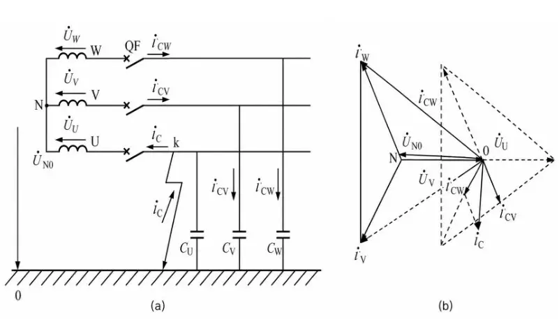
Open-delta voltage behavior: In this system, the neutral point displacement voltage equals the phase voltage (approx. 5.77kV). When reflected in the open-delta connection, the induced voltages from the residual windings sum up to produce a stable 100V output at the open-delta terminals. If the protection device is set to a threshold of 20V, detecting this 100V signal immediately triggers an alarm and issues a “busbar ground fault” signal, alerting operations and maintenance personnel to investigate the fault.
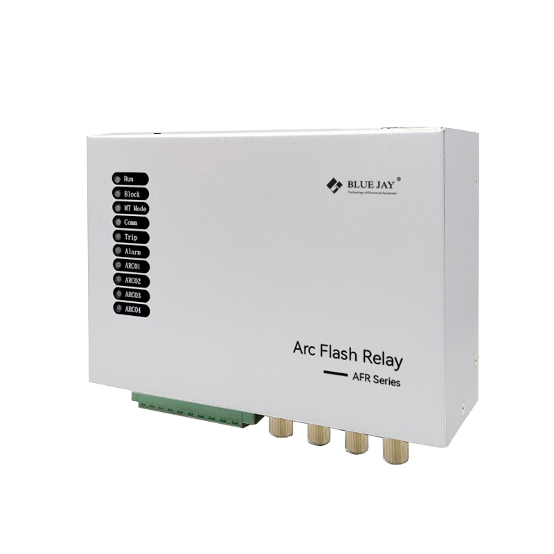
System characteristics: The fault current consists of the total system capacitive current to ground. In a 10kV distribution network with extensive cabling, the capacitance to ground is significant, and the fault current can reach tens of amperes. This condition easily leads to intermittent arcing at the fault location, causing arc-induced overvoltage; in severe cases, this can puncture equipment insulation and pose safety risks. We offer arc protection relays specifically designed to address this issue.
Open-delta PT connection in a system with neutral grounded via an arc-suppression coil
In a system where the neutral point is grounded via an arc-suppression coil, an inductive coil—the arc-suppression coil—is connected between the system neutral and the earth to compensate for capacitive current during a ground fault. Taking a 10kV system grounded via an arc-suppression coil as an example: an arc-suppression coil (inductor) with a rated current of 50A is connected between the neutral and the earth to compensate for the capacitive current during a ground fault; the inductive current of the coil flows in the opposite direction to the system’s capacitive current to earth.
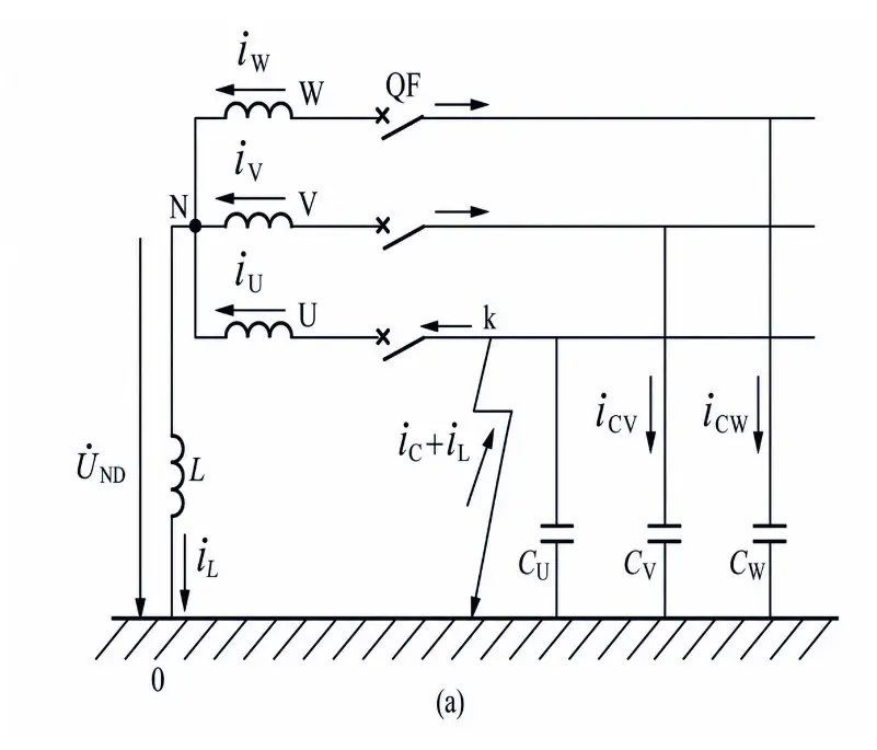
Primary-side voltage changes: These are identical to those in an ungrounded system. Taking a solid ground fault on Phase C as an example: the voltage to earth of the faulted phase (Phase C) drops to zero, while the voltages to earth of the healthy phases (Phases A and B) rise to the line voltage of 10kV; the pattern of voltage change remains the same.
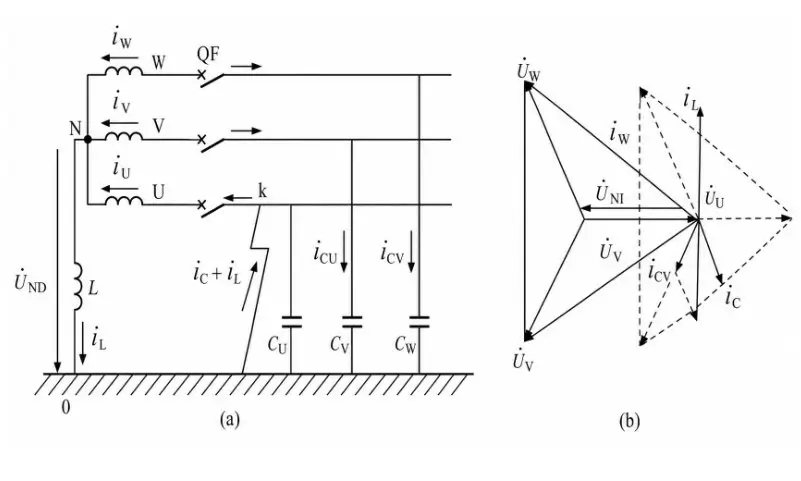
Open-delta voltage behavior: This is consistent with an ungrounded system; during a solid ground fault, the open-delta winding outputs a stable 100V. For instance, in the aforementioned 10kV system, the arc-suppression coil compensates only for the fault current and does not alter the magnitude of the system’s zero-sequence voltage; consequently, the voltage signal monitored at the open-delta winding remains unchanged, allowing for the reliable triggering of a ground fault alarm.
Core system characteristics (key differences from an ungrounded system):
Significantly reduced fault current: Taking the aforementioned 10kV system as an example, if the system’s capacitive current to earth is 40A and the arc-suppression coil provides 50A of inductive current, the two currents cancel each other out, leaving a residual current of only 10A at the fault location. This allows the arc to extinguish easily on its own, preventing overvoltages caused by intermittent arcing.
– Higher power supply reliability: Due to the low fault current and the ease with which the arc extinguishes, the system can continue to operate with the fault present for 1–2 hours. This buys time for operations and maintenance personnel to locate and rectify the fault, avoids losses associated with power outages, and enhances the stability of the power supply.
– Increased difficulty in fault line selection: Taking this system as an example, after the zero-sequence current of the faulty line is compensated by the arc-suppression coil, its amplitude drops from 40 A to 10 A, and its directional characteristics become less distinct. Conventional zero-sequence current-based selection devices cannot accurately identify the faulty line; instead, small-current grounding fault selection devices are required for precise localization.
Conclusion
In both types of grounding systems, the open-delta winding outputs a 100V zero-sequence voltage for alarm purposes during a single-phase ground fault; the distinction lies solely in whether the fault current is compensated by an arc-suppression coil. Compensated systems offer superior arc-extinguishing capabilities and more stable power supply, albeit at the cost of increased difficulty in locating the faulty line. The open-delta winding serves as a core component for grounding monitoring in distribution networks and forms the foundation of the insulation monitoring system for small-current grounding networks.